Audit your current HVAC fan energy consumption
Before making any changes, establish a reliable baseline. Without measured data, you cannot calculate savings, justify investment decisions, or identify which fans offer the greatest opportunity. An energy audit is the foundation of every successful HVAC fan energy savings project.
- Identify every fan in scope: supply air, return air, exhaust, cooling tower, and chiller fans. List their rated motor power in kilowatts and their operating hours per day and per year.
- Install temporary power meters or use existing metering infrastructure to record actual electrical consumption for each fan over a representative period, ideally two to four weeks covering varying load conditions.
- Record operating conditions alongside power data: ambient temperature, occupancy schedules, process load variations, and any seasonal patterns that affect ventilation demand.
- Calculate the load factor for each fan by comparing measured shaft power to the motor's rated power. A fan consistently drawing 60 to 70 percent of rated power is a strong candidate for variable speed control.
After completing the audit, you should have a ranked list of fans by energy consumption and by the gap between their current output and actual system demand. Fans where that gap is widest represent your highest-priority targets. Keep this data accessible because you will reference it at every subsequent step.
Match fan output to actual system demand
Most HVAC fans are sized for peak design conditions that occur only a fraction of the time. The rest of the time, they deliver excess airflow that the system throttles away through dampers or that simply goes to waste. Matching fan output to real demand is the single most impactful lever for reducing HVAC energy consumption, because fan power follows the cubic affinity law: reducing fan speed by just 20 percent cuts shaft power by nearly 50 percent.
Start by reviewing your system's design specifications against the measured operating data from your audit. In many facilities, the design safety margins applied during the original engineering phase, combined with years of operational drift, mean fans are running significantly above what the process actually needs.
- Map your ventilation demand profile across a full operating cycle, including peak, average, and minimum load periods. Express demand as a percentage of the fan's rated output.
- Identify the percentage of operating hours spent below 80 percent of rated output. If this figure exceeds 40 to 50 percent of runtime, variable speed operation will deliver substantial savings.
- Determine whether demand varies continuously (requiring true variable speed control) or whether the system operates reliably at two or three distinct set points (where multi-speed or staged control may suffice).
- Check whether existing damper or valve throttling can be eliminated once speed control is introduced, as removing these restrictions reduces system resistance and improves overall efficiency further.
The output of this step is a demand profile that directly informs your choice of speed control method. A fan that runs at 60 percent of rated speed for the majority of its operating hours is a fundamentally different investment case from one that fluctuates continuously between 40 and 100 percent. Knowing which situation you are dealing with prevents over-engineering and keeps project costs proportional to the actual opportunity.
Choose the right speed control method for your setup
With your demand profile defined, you can select the speed control method that best fits your application, environment, and budget. There is no universal answer: the right choice depends on your power range, the physical environment of the installation, and the total cost you are prepared to carry over the asset's lifetime.
Variable frequency drives
Variable frequency drives (VFDs) are the most widely deployed electronic speed control solution for HVAC fans. They are well suited to fans below 10 kW and to applications where precise, continuously variable speed control is required across a wide range. However, VFDs carry system-level parasitic losses that are frequently underestimated. Published efficiency figures of 96 to 98 percent apply only to the power electronics at rated load under new and clean conditions. A complete power drive system, including MCC distribution, input filters, line reactors, output filters, motor cables, and additional motor losses, typically adds 8 to 12 percent in baseline system losses, rising to 14 to 24 percent over the system's lifetime as environmental contamination and component aging accumulate. Factor these losses into your economic model before committing.
Non-contact magnetic drives
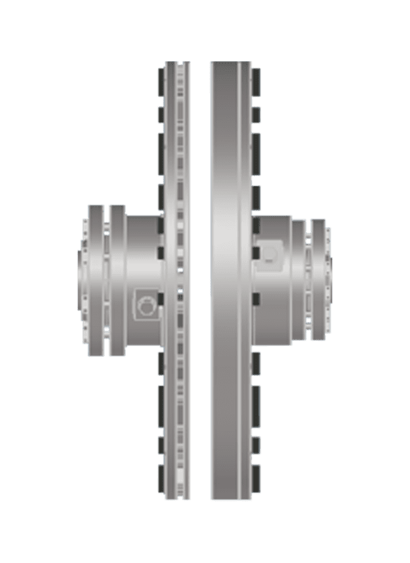
For fans in the 10 to 375 kW range, a mechanical variable speed solution such as a non-contact drive offers an alternative that eliminates the electronic loss stack entirely. These devices use powerful permanent magnets to transmit torque without physical contact between the motor and the driven shaft, providing continuously variable speed from zero to approximately 98 percent of motor rated speed. Because there are no power electronics in the drivetrain, the system-level parasitic losses associated with VFDs do not apply. This is particularly relevant in HVAC plant rooms where dust, humidity, and temperature variation accelerate electronic aging.
Selecting between approaches
- Below 10 kW: a VFD is generally the practical choice due to the physical size constraints of mechanical drives at low power.
- 10 to 375 kW in standard environments: evaluate both VFDs and non-contact drives on total installed cost and lifetime operating cost, not purchase price alone.
- Above 375 kW: project-specific evaluation is required; both technologies are viable depending on application specifics.
- Hazardous area (ATEX Zone 1 or Zone 2): VFDs require installation in a separate safe area room with dedicated climate-controlled HVAC, inverter-duty motors, and shielded cabling, all of which add significant cost and complexity. A non-contact drive installed in the hazardous zone reuses the existing Ex-rated motor and existing power cabling, with only an ATEX-certified actuator added in the zone.
Document your selection rationale, including the power range, environment classification, demand profile, and cost comparison. This record supports the business case approval and provides a reference point when you reach the verification step.
Install and configure your chosen drive solution
Installation quality determines whether the energy savings you calculated on paper are actually realized in operation. Regardless of which speed control method you have chosen, careful execution at this stage prevents common issues including mechanical vibration, control instability, and premature component wear.
Preparing for installation
- Confirm that the motor's rated power and speed match the drive solution's selection range. For non-contact drives, verify the air gap specification (typically 3 to 35 mm depending on the model) and confirm hub and shaft dimensions against the drive's dimensional data.
- Review the existing motor cabling. If you are installing a VFD, determine whether the existing cable meets VFD-rated shielded cable requirements; replacement is often necessary and adds significant cost. For non-contact drives, existing cabling is reused without modification.
- Confirm that the control system integration path is clear: what signal will command speed changes, what feedback loop closes the control, and how does the drive communicate status to the building management or SCADA system.
Commissioning the drive
- Set minimum and maximum speed limits based on your demand profile. For most HVAC fans, a minimum speed of 30 to 40 percent of rated speed prevents stall conditions and maintains adequate airflow for ventilation requirements.
- Configure the control response: proportional-integral control loops for pressure or flow setpoints are standard for HVAC fan applications. Tune the response to avoid hunting between speed set points, which wastes energy and accelerates wear.
- Run the fan through its full speed range under no-load and then under live system conditions, recording power consumption, airflow, and any vibration or noise anomalies at each speed increment.
- Verify that all safety interlocks, thermal protection, and alarm functions operate correctly before handing the system back to operations.
After commissioning, record the baseline power consumption at the operating set points you have configured. This is the post-installation baseline against which you will measure actual savings, and it is distinct from the pre-installation baseline you captured during the audit.
Verify savings and fine-tune fan performance
Measuring actual savings closes the loop between the investment decision and the outcome. It also reveals whether the system is performing as modeled or whether adjustments are needed to capture the full efficiency opportunity.
- Compare metered energy consumption at each fan over the first four to eight weeks of operation against the equivalent period from your pre-installation audit data. Normalize for any differences in operating hours or ambient conditions.
- Review the speed distribution histogram if your drive solution logs operating data. Confirm that the fan is spending the majority of its time at the reduced speeds your demand profile predicted, not defaulting to higher speeds due to control set point drift or changed system conditions.
- Check airflow and pressure measurements against the system design targets. If airflow is lower than required at the configured speed set points, investigate whether dampers or filters have increased system resistance, which would require a set point adjustment.
- Recalculate the projected payback period using actual measured savings rather than modeled estimates. If savings are below expectations, identify the gap: is it in the demand profile assumption, the system resistance, or the drive's operating configuration?
Fine-tuning at this stage often yields an additional 5 to 15 percent improvement over the initial commissioning result. Common adjustments include tightening the pressure setpoint, lowering the minimum speed limit if system conditions allow, and removing residual damper restrictions that are no longer needed once variable speed control is active. Document every adjustment and its measured effect so that the system's optimal configuration is captured for future reference.
Reduce HVAC fan maintenance to sustain long-term savings
Energy savings erode over time if the mechanical condition of the drivetrain degrades. Worn bearings, misaligned shafts, and contaminated components all increase the power required to deliver a given airflow. A maintenance strategy aligned with your drive technology protects the investment you have made and keeps the system performing at the efficiency level you verified in the previous step.
- Establish a condition monitoring schedule for fan bearings, including vibration measurement and temperature trending. Catching bearing degradation early prevents the cascading failures that cause unplanned downtime and can damage the fan impeller or motor.
- Inspect and clean air filters on a schedule tied to the actual contamination rate in your plant environment, not a fixed calendar interval. Blocked filters increase system resistance and force the fan to work harder to maintain the same airflow.
- Check shaft alignment at each planned maintenance interval if you are using a conventional mechanical coupling. Misalignment is one of the leading causes of bearing and seal failure in fan systems.
- Review drive component condition annually. For VFD-driven systems, this includes checking electrolytic capacitor health, cooling fan operation, and filter condition, as these components age and degrade in the plant room environment.
The maintenance burden varies significantly depending on the drive technology in place. Conventional mechanical couplings require regular lubrication, alignment checks, and wear component replacement. Non-contact magnetic drives eliminate physical contact between the motor and fan shaft entirely, which removes lubrication requirements and eliminates the alignment sensitivity that drives much of the maintenance workload in traditional fan installations. This is a meaningful factor when calculating the total cost of ownership over a ten to fifteen year asset life.
How Zytec helps you save energy on HVAC fans
Zytec's non-contact drives are purpose-built for exactly the kind of rotating equipment optimization this guide describes. For HVAC fan applications in the 10 to 375 kW range, the V-TORQ and A-TORQ non-contact drives deliver continuously variable speed control without the electronic loss stack, cabling requirements, or component aging that characterize VFD-based solutions. Key advantages for HVAC applications include:
- Energy savings up to 50% by matching fan speed precisely to actual ventilation demand, with no parasitic losses from power electronics in the drivetrain
- Vibration reduction up to 80% through the inherent shock-absorbing characteristics of magnetic torque transmission, protecting fan bearings and extending service life
- Zero coupling maintenance over a rated lifespan exceeding 20 years, eliminating lubrication, alignment checks, and wear component replacement from the maintenance schedule
- Reuse of existing motors and cabling, which significantly reduces installation cost and project timeline compared to VFD retrofits that require inverter-duty motors and shielded cable replacement
- Payback periods typically under two years based on documented energy and maintenance cost reductions across industrial HVAC installations
If you are ready to move from the audit and planning steps in this guide to a concrete solution for your facility, contact Zytec to discuss your specific fan application. The team can provide a technical and economic assessment tailored to your power range, environment, and operational profile, so you can make an informed investment decision backed by real performance data.
Frequently Asked Questions
How do I know if my HVAC fans are good candidates for variable speed control without conducting a full energy audit first?
A quick preliminary check can help you prioritize before committing to a full audit. If your fans run continuously at fixed speed, use inlet guide vanes or discharge dampers to regulate airflow, or were installed with generous design safety margins (common in facilities built more than ten years ago), they are strong candidates. As a rule of thumb, any fan spending more than 40 percent of its runtime below 80 percent of rated output will likely deliver a compelling return on variable speed investment.
What is the cubic affinity law and how much of a real-world difference does it actually make to fan energy savings?
The cubic affinity law states that fan shaft power varies with the cube of the fan speed ratio, meaning a relatively small speed reduction produces a disproportionately large reduction in energy consumption. For example, reducing fan speed by 20 percent cuts shaft power by approximately 49 percent, and a 30 percent speed reduction cuts power by nearly 66 percent. In practice, real-world savings are slightly lower than the theoretical curve due to system resistance and drivetrain losses, but the relationship is robust enough that even modest, sustained speed reductions deliver substantial annual energy cost reductions.
What are the most common mistakes facilities make when retrofitting HVAC fans with speed control, and how can I avoid them?
The three most frequent mistakes are underestimating total installed cost by focusing on purchase price alone, failing to remove existing damper restrictions after variable speed control is introduced (which negates a significant portion of the savings), and selecting a control method based on a single operating condition rather than the full demand profile. Avoid these by building a lifetime cost model that includes cabling, installation, maintenance, and component aging, commissioning the system with dampers fully open, and mapping your demand profile across all operating modes before specifying the drive solution.
Can variable speed control be applied to HVAC fans in hazardous or classified areas, and what are the key considerations?
Yes, but the approach differs significantly depending on the technology chosen. VFDs must be installed outside the hazardous zone in a separate, climate-controlled safe area enclosure, which requires dedicated infrastructure, ATEX-rated inverter-duty motors, and shielded cabling throughout the zone — all of which add considerable cost and complexity. Non-contact magnetic drives rated for hazardous area installation can be mounted directly in the zone, reusing the existing Ex-rated motor and existing power cabling, with only an ATEX-certified actuator added. This makes them a materially simpler and often lower-cost solution for classified environments.
How long does it typically take to see a return on investment from an HVAC fan optimization project?
Payback periods vary with fan size, operating hours, local energy tariffs, and the drive technology selected, but well-executed projects on fans in the 10 to 375 kW range commonly achieve payback within one to two years. The key drivers of a shorter payback are high annual operating hours (fans running 6,000 hours or more per year), a large gap between current operating speed and actual demand, and a drive solution with low installation cost — for example, one that reuses existing motors and cabling rather than requiring full replacement. Using your measured audit data rather than estimated figures in the economic model will give you the most reliable payback projection.
How do I maintain the energy savings over time and prevent performance from degrading after the initial optimization?
The primary threats to sustained savings are increased system resistance (from blocked filters or partially closed dampers), mechanical degradation (bearing wear, shaft misalignment), and, for VFD-driven systems, electronic component aging that increases parasitic losses. Counter these by tying filter inspection intervals to actual contamination rates rather than fixed calendars, scheduling periodic vibration and alignment checks, and reviewing drive operating data quarterly to confirm the fan is still spending the majority of its runtime at the reduced speeds your demand profile predicted. Re-running a simplified version of the original energy audit every two to three years provides an objective check on whether savings are holding.
Is it worth optimizing smaller HVAC fans below 10 kW, or should I focus exclusively on larger units?
Larger fans almost always offer the highest absolute energy savings per unit and should be prioritized first, but smaller fans should not be ignored entirely if they operate in large numbers or at very high annual hours. A practical approach is to address fans above 10 kW individually with tailored drive solutions, then assess whether a standardized VFD rollout across smaller fan populations makes sense based on aggregate consumption data from your audit. For facilities with dozens of small fans running continuously, the cumulative savings can be significant even if the per-unit return is modest.