Identify the root causes of equipment failure
Before you can improve critical equipment reliability, you need to understand why failures are actually happening. Many maintenance teams treat symptoms rather than causes, replacing bearings or seals without asking what damaged them in the first place. A structured root cause analysis changes that pattern.
Start by auditing your maintenance history for the past 12 to 24 months. Look for recurring failure modes on the same assets, and pay close attention to the timing and sequence of events leading up to each failure. The most common root causes in rotating equipment are misalignment, vibration, lubrication issues, and overloading. Of these, misalignment alone is responsible for a significant share of rotating machinery failures and a substantial portion of breakdown costs across industrial plants.
- Pull maintenance records for all critical rotating assets and categorize failures by type: bearing failure, seal failure, coupling damage, shaft damage, or other.
- For each recurring failure, trace back to the operating condition that preceded it: was the machine recently realigned, restarted after maintenance, or running under variable load?
- Map the failure chain: identify whether the root cause is mechanical, operational, or installation-related.
- Prioritize assets by criticality and failure frequency to focus your improvement effort where it delivers the most value.
Once you have a clear picture of where and why failures originate, you have the foundation to make targeted changes rather than broad, expensive interventions. Verify this step by producing a short list of the top three to five failure drivers across your critical equipment. These become your targets for the steps that follow.
Eliminate mechanical contact from the drive train
Mechanical contact between drivetrain components is a primary source of wear, vibration, and failure in rotating equipment. Traditional couplings, whether jaw, gear, grid, or elastomeric, all rely on physical contact to transmit torque. That contact degrades over time, introduces misalignment forces into bearings and seals, and requires regular inspection, lubrication, and element replacement.
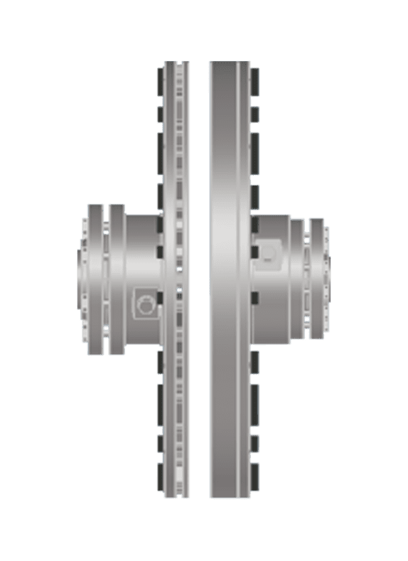
The most effective way to eliminate these failure mechanisms is to remove mechanical contact from the drivetrain entirely. Non-contact magnetic drives transmit torque across an air gap using powerful permanent magnets, with no friction, no elastomers, no lubrication, and no wear components. This is not a marginal improvement: it removes the entire category of coupling-induced failures from your maintenance equation. The torque transmission characteristics of a magnetic coupling do not degrade with age, temperature, or accumulated operating hours, giving it an expected service life that spans the full lifetime of the installation.
To evaluate whether eliminating mechanical contact is feasible for your application, follow these steps:
- Identify the coupling type currently installed on each critical asset and document its inspection interval, last replacement date, and any associated alignment history.
- Assess the misalignment conditions the coupling is exposed to: static installation offset, thermal expansion during operation, pipe strain, and foundation movement. These dynamic misalignment forces are often two to five times greater than installation tolerances suggest.
- Determine whether the application involves shock loads, high inertia starts, or variable torque demand, as these are conditions where contact coupling wear accelerates fastest.
- Review whether a non-contact solution can be retrofitted using existing motor, cabling, and mounting infrastructure to minimize installation cost and complexity.
After completing this assessment, you should be able to identify which assets are the strongest candidates for a contactless drivetrain upgrade. A magnetic drive installed correctly requires no scheduled coupling maintenance and no laser alignment, which structurally reduces the number of human interventions near rotating equipment over the life of the asset.
Reduce vibration to protect connected assets
Vibration is both a symptom and a cause of equipment degradation. Coupling-induced torsional oscillations, misalignment forces, and resonance events all accelerate wear on bearings, seals, gearboxes, and structural interfaces. Reducing vibration at the source protects every component downstream and extends the time between failures across the entire drivetrain.
Begin by establishing a vibration baseline on your critical equipment using portable vibration measurement tools or permanently installed sensors. Measure at the bearing housings on both the motor and driven sides, and record readings at multiple operating points, including startup, full load, and partial load. Compare your measurements against ISO 10816 or ISO 20816 acceptance criteria for the equipment class.
- Measure overall vibration velocity (mm/s RMS) and acceleration (g) at each bearing location and record the dominant frequency components using a spectrum analyzer.
- Identify the vibration source by correlating frequency peaks with running speed harmonics, blade pass frequencies, or coupling mesh frequencies.
- Address soft-foot conditions, pipe strain, and foundation issues before adjusting alignment, as these are often overlooked contributors to elevated vibration.
- If the coupling is the primary vibration source, evaluate whether eliminating mechanical contact would remove the excitation entirely rather than simply dampening it.
- Re-measure after any intervention and compare against your baseline to confirm the improvement is real and quantified.
Vibration reduction up to 80% is achievable when the root cause is coupling-induced excitation and the drivetrain is upgraded to a contactless solution. More stable load conditions downstream mean bearings and seals operate with less stress, extending their service intervals and reducing the probability of cascading failures during operation.
Adjust load control to match actual process demand
Many industrial systems are designed with overcapacity built in as a safety margin. Pumps and fans sized for peak demand run at full speed even when the process requires only a fraction of that output. The excess energy is throttled away through valves or dampers, wasting power and adding unnecessary mechanical stress to the drivetrain. Matching load output to actual process demand is one of the most direct ways to reduce both energy consumption and equipment wear simultaneously.
The relationship between speed and power in centrifugal applications follows the affinity laws: reducing speed by 20% reduces shaft power by roughly 50%. This means even modest speed reductions deliver significant energy savings. Variable speed control, whether electronic or mechanical, allows the system to deliver exactly what the process needs rather than running at full output continuously.
- Audit the actual operating profile of each pump or fan: what percentage of operating hours does the system run at full load, partial load, or near-zero demand?
- Quantify the current throttling loss by measuring the pressure drop across control valves or dampers during normal operation. This represents recoverable energy.
- Evaluate variable speed options appropriate to your application, including electronic variable frequency drives and mechanical variable speed solutions such as non-contact magnetic variable drives.
- For hazardous area applications, assess the full installed cost of each option, including associated electrical infrastructure, cable upgrades, and compliance requirements, not just the drive unit price.
- Implement the selected speed control solution and verify energy consumption before and after using power meters at the motor input terminals.
After implementing variable speed control on a pump or fan system, you should see measurable reductions in both electricity consumption and drivetrain vibration at partial load. Confirm the improvement by comparing monthly energy data against your pre-installation baseline and checking vibration levels at the new operating speeds.
Validate reliability gains and track performance over time
Implementing changes to your drivetrain and load control strategy is only half the work. Without structured performance tracking, it is impossible to confirm that reliability has actually improved, identify whether further optimization is needed, or build the business case for expanding the approach to other assets. This final step turns one-time improvements into a continuous reliability program.
Define the key performance indicators you will track before any changes are made, so you have a clean baseline for comparison. The most useful metrics for rotating equipment reliability are mean time between failures (MTBF), overall equipment effectiveness (OEE), maintenance labor hours per asset per year, energy consumption per unit of output, and vibration trend data from periodic or continuous monitoring.
- Record baseline values for each KPI on every modified asset before the improvement is implemented.
- Set a review schedule: monthly for vibration and energy data, quarterly for maintenance cost and downtime, annually for a full TCO assessment.
- Use the PF curve framework to assess whether your interventions have extended the detectable degradation window. A longer PF interval means more time to respond before functional failure occurs.
- Document every maintenance event, its cause, and the time taken. Over 12 to 24 months, the trend in maintenance event frequency is the clearest indicator of whether reliability has improved.
- Share results across organizational levels, from plant floor to management, to maintain commitment and identify further improvement opportunities.
The goal is not a single improvement event but a self-reinforcing cycle: better data leads to better decisions, which leads to fewer failures, which frees up resources for further optimization. Plants that track reliability systematically consistently outperform those that manage maintenance reactively, and the performance gap widens over time.
How Zytec helps improve critical equipment reliability
Zytec develops non-contact magnetic drives that address the root causes of rotating equipment failure described throughout this guide. Rather than managing the consequences of mechanical wear, misalignment, and vibration, Zytec's technology removes the failure mechanisms entirely by transmitting torque across an air gap with no physical contact. The practical results are significant:
- No coupling maintenance required: Zytec's non-contact drives contain no elastomers, no lubrication systems, and no wear components, delivering a maintenance-free operational span of 20 or more years.
- Misalignment tolerance by design: The drives accommodate up to 12 mm of radial dynamic misalignment without introducing forces into bearings or seals, eliminating alignment-induced failures.
- Vibration reduction up to 80%: By removing coupling-induced torsional oscillations from the drivetrain, connected assets operate under more stable load conditions.
- Energy savings up to 50%: The A-TORQ and V-TORQ product lines enable precise load control matched to actual process demand, eliminating overcapacity losses in pumps and fans.
- Short payback period: Total cost of ownership is reduced through elimination of wear consumables, laser alignment, and unplanned downtime, with payback periods often under two years.
If your operation depends on reliable rotating equipment and you are ready to move from reactive maintenance to a proactive reliability strategy, contact Zytec to discuss which non-contact drive solution fits your application.
Frequently Asked Questions
How do I know which of my rotating assets should be prioritized first for reliability improvements?
Start by ranking your assets using two criteria: criticality to production (what happens if this asset fails?) and failure frequency (how often has it failed in the past 12–24 months?). Assets that score high on both dimensions — meaning they fail often and their failure stops production — should be your first targets. A simple 2x2 criticality matrix can help you visualize this ranking and build a defensible prioritization list for your maintenance team and management.
What are the most common mistakes maintenance teams make when trying to reduce equipment downtime?
The most common mistake is treating symptoms rather than root causes — for example, replacing a bearing without investigating why it failed prematurely in the first place. A close second is relying on time-based replacement intervals rather than condition-based data, which leads to either over-maintaining assets that are still healthy or under-maintaining ones that are already degrading. A third frequent error is skipping baseline measurements before implementing changes, which makes it impossible to confirm whether an intervention actually worked.
How difficult is it to retrofit a non-contact magnetic drive onto existing equipment?
In most cases, a magnetic drive can be retrofitted using the existing motor, baseplate, and mounting infrastructure, which significantly reduces installation cost and complexity. The key variables to assess upfront are shaft size, torque requirements, and the available space envelope between the motor and driven equipment. Working with the drive manufacturer during the evaluation phase — rather than after purchase — ensures the selected solution is properly matched to your application and that no unexpected civil or electrical modifications are required.
Can vibration monitoring be implemented without investing in expensive permanent sensor systems?
Yes. A cost-effective starting point is a portable vibration analyzer used on a defined route-based schedule — typically monthly or quarterly on critical assets. Route-based monitoring with a handheld instrument gives you trended data over time, which is sufficient to detect developing faults well before functional failure occurs. Permanent, continuously monitored sensor systems are best reserved for your highest-criticality assets where the consequence of missing a developing fault is particularly severe.
How long does it typically take to see measurable reliability improvements after implementing these steps?
Energy savings and vibration reductions are typically measurable within the first one to three months after a drivetrain or speed control upgrade, since these are direct physical changes with immediate effects. Reliability gains measured in MTBF and reduced maintenance labor take longer to confirm — expect 12 to 24 months of post-implementation data before the trend is statistically meaningful. This is why establishing a clean baseline before any changes are made is so important: it gives you an accurate reference point for comparison.
Do variable speed drives and magnetic drives work together, or do you have to choose one or the other?
They address different problems and can work together depending on the application. An electronic variable frequency drive (VFD) controls motor speed electronically, while a mechanical magnetic variable drive (such as Zytec's V-TORQ) achieves speed control mechanically across an air gap with no electrical infrastructure changes required. In some configurations, both technologies can be combined. The right choice depends on your application's torque profile, hazardous area classification, existing electrical infrastructure, and total installed cost — factors that should be evaluated together rather than in isolation.
How do I build a business case for reliability improvements when my management focuses primarily on upfront costs?
Frame the conversation around total cost of ownership (TCO) rather than purchase price alone. Calculate the fully loaded cost of a single unplanned failure event — including lost production, emergency labor, expedited parts, and any secondary damage — and compare that against the annualized cost of the proposed improvement. In most industrial operations, a single avoided failure event pays for the improvement investment entirely. Supporting this with 12–24 months of post-implementation KPI data (MTBF, energy consumption, maintenance hours) transforms the business case from a projection into a proven result.