What you need before upgrading your pump
Before touching the drivetrain, gather the information and materials that will define the scope and success of the upgrade. Skipping this preparation stage is the most common reason retrofits stall mid-project or fail to deliver their expected savings.
You will need the following documentation and resources:
- Motor nameplate data: rated power (kW), speed (rpm), frame size, voltage, and ATEX classification if applicable
- Pump curve and current operating point: flow rate, head, and shaft power at typical load
- Existing coupling type and dimensions: jaw, pin-and-bush, gear, fluid-flex, or other
- Shaft dimensions and distance between shaft ends (DBSE)
- Operational history: maintenance records, alignment logs, bearing and seal replacement frequency
- Site classification: whether the installation is in an Ex Zone 1 or Zone 2 hazardous area
- Access to the drive end of the motor and pump for measurement and installation
Having this data assembled before proceeding means you can complete the selection and installation phases without unplanned delays. If maintenance records show frequent bearing or seal failures, note the failure intervals, as these will form your baseline for measuring improvement after the upgrade.
Assess your pump's performance baseline
Establish a clear, quantified picture of how the pump is performing right now. This baseline is what you will compare against after the upgrade to confirm the results and build a business case for further rollout.
- Measure actual motor power draw using a clamp meter or power analyzer at the MCC, recording values across several operating conditions including peak load, average load, and minimum load.
- Log pump flow and pressure at each measurement point using existing instrumentation or portable flow meters if permanent sensors are not installed.
- Calculate hydraulic efficiency by comparing actual shaft power to the theoretical power required for the measured flow and head.
- Record vibration levels at the motor and pump bearings using a portable vibration analyzer, noting dominant frequencies and overall velocity (mm/s RMS).
- Document the current speed control method: fixed speed with throttle valve, bypass control, or existing variable frequency drive (VFD).
After completing this assessment, you should have a clear picture of where energy is being wasted. Throttle-controlled centrifugal pumps running at fixed speed are among the most common candidates for a magnetic drive pump retrofit, since they consume full motor power regardless of actual process demand. Systems where the pump is consistently throttled back by 20% or more are strong candidates for significant energy savings through variable speed control.
Select the right non-contact drive for your application
Selecting the correct magnetic drive for your pump is a straightforward process when you have the motor and pump data from the previous steps. Unlike conventional couplings, non-contact magnetic drives do not require service factor calculations because torque peaks and torsional vibration cannot generate shock loads within the coupling. Selection is based directly on motor power and speed.
Work through the following selection criteria:
- Identify whether you need a fixed-speed coupling (F-TORQ) or a variable-speed drive (V-TORQ or A-TORQ). If your baseline assessment showed the pump is consistently throttled, choose the variable-speed option to unlock energy savings by reducing pump speed to match actual demand.
- Match the motor power (kW) and rated speed (rpm) to the appropriate frame size in the product selection table, covering standard IEC 50 Hz motors at 750, 1,000, 1,500, and 3,000 rpm and NEMA 60 Hz motors at 900, 1,200, 1,800, and 3,600 rpm.
- Check the torque level designation required: Standard, HT (High Torque), or XT (Extreme Torque). For high-inertia pump applications, the F-TORQ.HI variant is designed as a direct upgrade for fluid-plus-flex starting couplings.
- Confirm the shaft dimensions and DBSE against the coupling dimensional data, including outer diameter, hub dimensions, and air gap range (standard range: 3 to 35 mm).
- If the installation is in an ATEX hazardous area, specify the EX variant. The non-contact drive contains no electronic components within the hazardous zone, which eliminates ignition risks and inverter-duty motor upgrade requirements associated with VFD installations in Ex environments.
One important advantage of this selection process is that the non-contact drive reuses your existing motor and power cabling. No inverter-duty motor upgrade is required, and no VFD-rated shielded cable replacement is needed, which removes two of the largest cost items typically associated with adding variable speed control to an existing pump installation.
Install the magnetic drive between motor and pump
Installation of a non-contact magnetic drive is designed as a drop-in retrofit for all conventional coupling types. The process reuses existing motor and cabling infrastructure and, critically, does not require laser alignment during installation, which removes one of the most time-consuming and skill-dependent steps in traditional coupling replacement.
Prepare the drivetrain
Begin by isolating the motor and following your site's lockout/tagout and permit-to-work procedures. Remove the existing coupling completely, including both hubs and any intermediate element. Clean and inspect both shaft ends for damage, corrosion, or fretting. Measure the shaft diameters precisely to confirm compatibility with the slip-fit, clearance-fit hubs supplied with the magnetic drive.
Mount the hubs and rotors
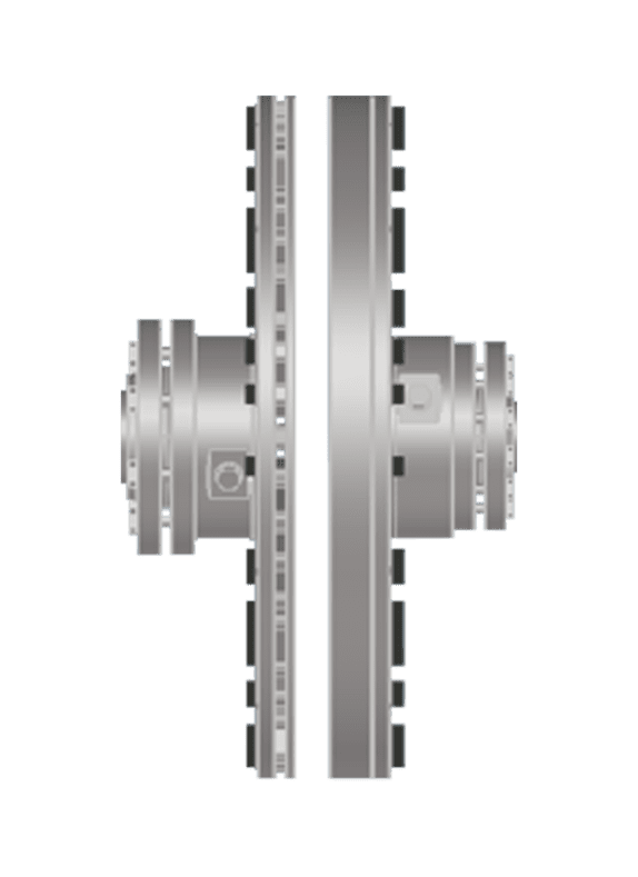
- Fit the Inductor Rotor hub to the motor shaft using the shrink disc mounting method specified in the installation manual. Tighten to the specified torque values.
- Fit the Magnet Rotor hub to the pump shaft in the same manner.
- Position the motor on the baseplate to achieve the correct air gap between the Inductor Rotor and Magnet Rotor. The air gap setting at this stage corresponds to the fixed operating speed for F-TORQ installations, or the starting position for variable-speed V-TORQ configurations.
- Verify the air gap is uniform around the full circumference using feeler gauges. Adjust the motor position axially until the gap is within the specified range.
Because the non-contact drive transmits torque across an air gap with no physical interface between the driving and driven sides, precise angular alignment is not required. This is a fundamental difference from all conventional flexible coupling types, which continue to transmit misalignment-induced reaction forces into bearings and seals even when the coupling element itself accommodates the offset. Once the air gap is set, the installation is mechanically complete on the coupling side.
Connect the variable-speed actuator (V-TORQ only)
For variable-speed installations, mount the Motor Sliding Base (MSB) according to the supplied drawings and connect the ATEX-certified actuator that controls axial motor position. Wire the actuator to the control system using the existing cable route where possible. The actuator operates on the same maintenance intervals as throttle valve actuators already present in the plant, so it integrates naturally into your existing maintenance schedule.
Commission and validate the upgraded pump
With the magnetic drive installed, commission the system carefully to confirm correct operation before returning the pump to full service. This step verifies that the installation has been completed correctly and establishes the post-upgrade performance baseline.
- Remove all lockout/tagout devices and restore power to the motor following site procedures.
- Start the motor and observe the startup behavior. The non-contact drive provides inherent soft-start characteristics because torque is transmitted magnetically rather than through a rigid mechanical connection, which reduces mechanical stress on the pump and driven equipment during each start.
- Measure motor power draw at the same operating conditions recorded during the baseline assessment in step two.
- Measure vibration levels at the motor and pump bearings and compare against baseline readings. A reduction in vibration is expected because misalignment-induced reaction forces have been eliminated at the source.
- For variable-speed installations, verify that the actuator responds correctly to control signals and that pump speed changes smoothly across the full operating range.
After commissioning, you should observe reduced vibration levels, smoother operation, and, for variable-speed configurations, measurable reductions in motor power draw when the pump is running below full demand. If vibration levels have not improved, check the air gap uniformity and confirm that the pump's own bearings and seals are in good condition, as the drive upgrade will reveal pre-existing mechanical issues that were previously masked by higher vibration from misalignment.
Optimize speed and load settings for maximum savings
The final step is where the majority of the energy savings from a pump retrofit are realized. For variable-speed installations, matching pump speed to actual process demand rather than running at full speed and throttling the output is the core mechanism behind energy reductions of up to 50%.
Centrifugal pumps follow the affinity laws: reducing speed to 80% of rated speed reduces shaft power demand to roughly 51% of full-speed power. This relationship means that even modest speed reductions produce significant energy savings, and the savings compound over long operating hours.
- Review the process demand profile over a representative operating period, identifying the minimum, average, and peak flow requirements.
- Set the control system to operate the pump at the minimum speed required to meet process demand at each operating condition, rather than at a fixed speed with downstream throttling.
- Remove or open any throttle valves that were previously used to control flow, as these introduce artificial pressure drop that the pump now works against unnecessarily.
- Monitor power consumption over the first two to four weeks of optimized operation and compare against the pre-upgrade baseline to quantify actual energy savings.
- Adjust control setpoints based on measured results, particularly if process demand varies seasonally or with production schedules.
With optimized speed settings confirmed and energy savings documented, you have a completed pump upgrade that delivers measurable performance improvements without replacing any major equipment. The payback period for non-contact drive retrofits is typically under two years when variable speed control replaces fixed-speed, throttled operation, and the elimination of mechanical coupling maintenance removes a recurring cost that is rarely captured in simple energy calculations but is significant over the asset lifecycle.
How Zytec helps with upgrading your pump without replacing it
Zytec's non-contact magnetic drives are purpose-built for exactly the retrofit scenario described in this guide. Whether you are upgrading a single centrifugal pump or rolling out a program across multiple installations, Zytec provides the technology and support to make each upgrade straightforward and measurable. Key advantages of choosing Zytec for your pump upgrade include:
- Drop-in retrofit compatibility: F-TORQ and V-TORQ drives replace all conventional coupling types without modifying the motor, pump, or existing power cabling
- No laser alignment required: Installation is faster and does not depend on specialist alignment contractors
- Variable speed without a VFD: The V-TORQ provides full variable-speed process control with no inverter-duty motor upgrade, no shielded cable replacement, and no electronic components in the hazardous zone
- Energy savings up to 50%: Achieved by matching pump speed to actual process demand rather than throttling at full speed
- Vibration reduction up to 80%: Misalignment forces are eliminated at the source, extending bearing and seal service life significantly
- ATEX-certified options: Available for Ex Zone 1 and Zone 2 installations across the full power range from 7.5 kW to 500 kW standard
- Payback typically under two years: Combined energy and maintenance savings deliver rapid return on investment
Contact Zytec to discuss your specific pump application and receive a tailored selection recommendation and TCO analysis for your installation.
Frequently Asked Questions
Can a magnetic drive retrofit work on any centrifugal pump, or are there applications where it is not suitable?
Magnetic drive retrofits are compatible with the vast majority of centrifugal pump installations, including end-suction, split-case, and multistage configurations, provided the motor and pump shafts are accessible from the drive end. The main limiting factors are motor power range and shaft geometry — Zytec's standard range covers 7.5 kW to 500 kW, which encompasses most industrial pump applications. Positive displacement pumps with high starting torque requirements should be evaluated individually, and the F-TORQ.HI variant is specifically designed to handle high-inertia startup scenarios.
How does variable speed control via a magnetic drive compare to installing a VFD on the same pump?
Both approaches reduce pump speed to match process demand and deliver energy savings through the affinity laws, but the implementation costs and constraints differ significantly. A VFD requires inverter-duty motor upgrades, VFD-rated shielded cable replacement, and introduces harmonic distortion and heat into the electrical system — costs that rarely appear in simple payback calculations but are substantial in practice. The V-TORQ magnetic drive achieves the same variable-speed outcome mechanically, with no changes to the motor or power cabling, no electronic components in the hazardous zone, and no EMC or harmonic compliance burden, making it the more practical and often lower total-cost solution for existing pump installations, particularly in ATEX environments.
What happens if the process demands more flow than the pump can deliver after the speed has been optimized?
The control system should always be configured to prioritize process demand, meaning the pump speed is increased to meet rising demand up to the maximum rated speed of the drive. The optimization step described in this guide sets the minimum operating speed, not a fixed speed — the pump still ramps up to full speed when process conditions require it. If your process regularly hits or exceeds the pump's maximum rated output, this is a sizing issue with the pump itself rather than a limitation of the magnetic drive, and a pump curve review would be the appropriate next step.
How do I know whether my energy savings are coming from the magnetic drive or from other factors after the upgrade?
This is exactly why the baseline assessment in step two is so important — without documented pre-upgrade power consumption figures measured at identical operating conditions, attributing savings accurately is difficult. After commissioning, measure power draw at the same load points recorded in the baseline and compare directly. For variable-speed installations, also compare operating hours at each speed setpoint against pre-upgrade throttle valve positions to isolate the speed-reduction savings from any other process changes. Most sites find it useful to run this comparison over a full four-week period to account for production schedule variation before reporting final savings figures.
Will the magnetic drive still protect the pump if there is a sudden mechanical jam or blockage downstream?
Yes — the non-contact torque transmission mechanism acts as an inherent torque-limiting device. Because torque is transmitted magnetically across an air gap, if the driven load suddenly exceeds the drive's torque capacity (for example, due to a blockage or seizure), the magnetic coupling will slip rather than transmitting the overload into the motor or pump shaft. This slip-at-overload behavior protects both the motor and the pump from mechanical damage in fault conditions, which is an advantage over rigid or semi-flexible couplings that transmit shock loads directly through the drivetrain.
What ongoing maintenance does the magnetic drive require after installation?
The non-contact magnetic drive has no wearing parts at the coupling interface — there is no coupling element, elastomeric spider, gear tooth, or fluid medium to degrade or replace. Routine maintenance is limited to periodic inspection of the air gap setting and, for V-TORQ variable-speed installations, servicing the actuator that controls axial motor position on the same schedule as other actuators in your plant. This absence of coupling maintenance is one of the recurring cost savings that is often underestimated in payback calculations but compounds significantly over the asset lifecycle.
If vibration levels do not improve after installation, what should I check first?
Start by verifying that the air gap is uniform around the full circumference of the drive — an uneven gap is the most common installation-related cause of residual vibration. If the air gap checks out, the next step is to inspect the pump's own internal components: worn wear rings, a damaged impeller, or failing pump bearings will generate vibration that the magnetic drive cannot eliminate because it originates on the driven side of the coupling. The post-upgrade commissioning step is specifically designed to reveal these pre-existing mechanical issues, which are often masked by the higher baseline vibration from misalignment in conventionally coupled systems.