Identify what shortens fan lifespan first
Before making any changes, understand what is actually wearing your fan down. Fan longevity problems almost always trace back to a small set of root causes, and treating the symptom without addressing the cause leads to repeated failures. Start by reviewing your maintenance history and looking for patterns.
The most common culprits in industrial fan reliability problems are:
- Mechanical coupling wear — elastomers, pins, and grid elements degrade over time and introduce torsional shock into the drivetrain
- Misalignment — even small installation offsets grow during operation as thermal expansion, pipe strain, and foundation movement shift the equipment relative to its original position
- Vibration — coupling-induced torsional oscillations and unbalanced loads accelerate bearing and seal wear
- Overcapacity operation — fans sized for peak demand and throttled at partial load waste energy and create unnecessary mechanical stress
- Maintenance-induced failures — incorrect bolt torque, imperfect re-alignment after service, and missed fasteners during reassembly are more common contributors to equipment problems than many facilities acknowledge
Once you have identified which of these factors is most active in your installation, you can prioritize the steps below accordingly. If your fan is suffering from multiple issues simultaneously, work through the steps in order — they build on each other.
Eliminate mechanical contact at the drive connection
The coupling between your motor and fan is one of the highest-wear points in the entire drivetrain. Conventional couplings — jaw, pin-and-bush, grid, gear, or fluid-flex types — all rely on physical contact to transmit torque. That contact degrades over time, introduces shock loads, and requires regular inspection and element replacement. Eliminating it is the single most impactful change you can make for industrial fan reliability.
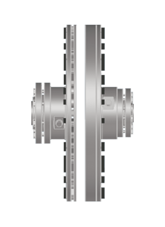
A non-contact drive transmits torque across an air gap using powerful permanent magnets. There are no elastomers to crack, no lubrication to maintain, and no wear components to replace. Because the magnetic field transmits torque without physical contact, torsional peaks and shock loads cannot propagate through the coupling into the fan shaft. The result is a fundamentally quieter drivetrain.
To transition from a conventional coupling to a non-contact magnetic drive:
- Record your motor power, rated speed, and shaft dimensions — these are the only inputs needed for coupling selection, with no service factor calculation required
- Confirm the available distance between shaft ends (DBSE) at your installation, as the air gap range for non-contact drives is typically 3 to 35 mm
- Select the appropriate coupling size from the manufacturer's catalogue tables, matched directly to motor power and speed
- Install using slip-fit, clearance-fit hubs and shrink disc mounting — no laser alignment is required during installation, as the non-contact design tolerates radial misalignment up to 12 mm dynamically
After installation, verify that the fan starts smoothly without mechanical shock and that there is no physical contact between the rotating elements. You should notice an immediate reduction in drivetrain noise compared to a worn conventional coupling.
Reduce vibration to protect fan bearings and housing
Vibration is one of the quietest destroyers of fan lifespan. It accelerates bearing fatigue, loosens structural connections, and degrades seals — often without triggering any alarm until the damage is already significant. Reducing vibration at the source protects every downstream component simultaneously.
The primary sources of vibration in fan drivetrains are misalignment, coupling-induced torsional oscillation, and imbalance. Misalignment is particularly insidious because it is not a static condition. Even a fan that is perfectly aligned at installation will experience dynamic misalignment during operation as the motor and fan housing expand at different rates under heat, as pipe connections exert strain on the casing, and as the foundation shifts seasonally. Conventional couplings resist this movement and transfer the resulting forces directly into bearings and seals.
A non-contact magnetic coupling has a radial stiffness of zero and a torsional stiffness of zero — meaning it does not resist or transmit misalignment forces at all. Dynamic misalignment passes through the air gap without generating bearing loads. Industry data from Zytec's engineering documentation shows vibration reductions of up to 80% in installations where the non-contact drive replaces a conventional coupling. This directly extends the P-F interval — the time between the point where bearing degradation becomes detectable and the point of functional failure — by approximately four times compared to installations using contact couplings.
To verify that vibration has been reduced after your drive change:
- Take baseline vibration readings at the fan bearings before the retrofit using a portable vibration analyzer
- Record readings at the same measurement points after installation under the same operating conditions
- Compare peak velocity and acceleration values — a meaningful reduction confirms that coupling-induced forces have been eliminated
- Schedule a follow-up reading at 30 days to confirm the improvement is stable
Match fan output to actual load demand
Many industrial fans are sized for maximum possible demand and then throttled back using dampers or inlet guide vanes for most of their operating life. This approach wastes significant energy and creates unnecessary mechanical stress. Fan energy efficiency improves dramatically when output is matched to actual load using variable speed control rather than mechanical throttling.
The physics behind this are straightforward. For fans, shaft power follows the cubic affinity law: halving fan speed reduces shaft power to one-eighth of its full-speed value. This means that a fan running at 70% of its rated speed uses less than half the energy it would at full speed. Mechanical throttling does not capture this benefit — it restricts airflow while the fan continues to work against the restriction.
Variable speed control eliminates this waste. For fans in standard environments, a variable speed drive reduces the motor's rotational speed to match actual airflow demand. For fans operating in hazardous or explosive atmospheres (ATEX zones), the choice of variable speed technology matters significantly — electronic variable frequency drives introduce ignition risks from power semiconductors, capacitors, and cooling fans, while a mechanical variable speed solution using a non-contact drive with an actuated air gap adjustment contains no electronic components within the hazardous zone.
To implement variable speed control effectively:
- Map your actual load profile over a representative operating period — identify what percentage of time the fan runs at various output levels
- Calculate the energy savings potential at each speed reduction point using the cubic law as a guide
- Select a variable speed solution appropriate for your environment, power range, and compliance requirements
- Set control limits to prevent the fan from running below its minimum safe operating speed, which varies by fan design
Once variable speed control is active, monitor energy consumption over the first month. A well-matched installation should show measurable reductions in electricity use, and the fan bearings and housing will experience lower mechanical stress at reduced speeds.
Verify your setup is working as intended
The steps above will significantly extend fan longevity and reduce fan downtime — but only if the installation continues to perform as designed over time. A simple monitoring routine confirms that the improvements are holding and catches any new issues before they become failures.
Establish a lightweight monitoring schedule that covers the key indicators of drivetrain health:
- Air gap — on a non-contact drive, changes in the air gap over time indicate system-level issues such as bearing degradation, pipe strain, or foundation settlement. Monitor it periodically as an early warning indicator.
- Vibration levels — periodic vibration readings at fan bearings confirm that the low-vibration condition established after the retrofit is being maintained
- Energy consumption — unexpected increases in power draw at a given fan speed can indicate aerodynamic fouling, bearing deterioration, or control system drift
- Temperature at bearings — elevated bearing temperature is one of the earliest detectable signs of lubrication failure or increased friction load
With your monitoring routine in place, you have a complete picture of fan health without relying on reactive maintenance. The goal is to catch the early signs of any new issue while the P-F window is still wide, giving you time to plan any intervention on your schedule rather than under emergency conditions. Fans maintained this way routinely exceed their design service life by a significant margin.
How Zytec helps with fan longevity and maintenance reduction
Zytec's non-contact magnetic drives address every major factor that shortens fan lifespan in a single engineered solution. For maintenance engineers and plant managers who want measurable results without complex change programs, the technology offers a direct and proven path to longer-running, lower-cost fan installations.
Here is what Zytec's non-contact drives deliver in fan applications specifically:
- Zero coupling wear — no elastomers, no lubrication, no scheduled coupling element replacement, with a maintenance-free service life rated at 20 or more years
- Vibration reduction up to 80% — bearing and seal loads are reduced from day one, extending component life across the entire drivetrain
- Energy savings up to 50% — variable speed capability matched to actual load demand reduces electricity consumption significantly
- Drop-in retrofit installation — existing motors and cabling are reused, no laser alignment is required, and installation is completed without extended downtime
- Payback periods often under two years — energy and maintenance savings combine to deliver a short return on investment
If your fans are consuming more energy than they should, generating recurring maintenance costs, or experiencing premature bearing failures, contact Zytec to discuss how a non-contact drive can be applied to your specific installation.
Frequently Asked Questions
How do I know if my fan is a good candidate for a non-contact magnetic drive retrofit?
Most industrial fans driving continuous or variable loads are strong candidates, particularly if you are seeing recurring bearing failures, high coupling replacement frequency, or elevated energy costs. The key technical inputs you need are motor power, rated speed, shaft dimensions, and available distance between shaft ends (DBSE). If your fan operates in an ATEX-classified hazardous zone, a non-contact mechanical drive is especially worth evaluating since it introduces no electronic components into the hazardous area.
What happens if there is a sudden overload or jam on the fan — will the magnetic coupling protect the motor?
Yes, and this is one of the practical safety advantages of a non-contact magnetic drive. Because torque is transmitted across an air gap using magnetic fields rather than a rigid mechanical connection, the coupling has a natural torque limit defined by its magnetic design. If the load exceeds this limit — for example, during a rotor jam — the magnets decouple rather than transmitting the shock load back through the motor shaft. This provides inherent overload protection without any additional mechanical safety device.
How much downtime is typically required to retrofit a non-contact drive onto an existing fan installation?
Retrofits are generally completed within a single planned maintenance window. Because no laser alignment is required and existing motors and cabling are reused, the installation process is significantly shorter than a full drivetrain replacement. Most installations are completed in a matter of hours rather than days, which means the retrofit can often be scheduled during a routine inspection stop rather than requiring a dedicated shutdown.
Can variable speed control damage a fan if it runs too slowly for extended periods?
Yes — running a fan below its minimum safe operating speed can cause aerodynamic instability, surge, or inadequate bearing lubrication depending on the fan design. This is why setting a lower speed limit in your control system is an essential step, not an optional one. Consult the fan manufacturer's documentation for the minimum continuous operating speed, and program your variable speed solution to enforce that limit as a hard floor regardless of demand signals.
My facility already uses vibration monitoring. How should I adjust my alert thresholds after installing a non-contact drive?
After the retrofit, take new baseline vibration readings under normal operating conditions — these will typically be significantly lower than your pre-retrofit baselines. Reset your alert and alarm thresholds relative to the new baseline rather than carrying over the old values. Using the old thresholds means you will either miss early deterioration signals (if thresholds are set too high relative to the new lower baseline) or generate false alarms during normal operation.
What is the most common mistake facilities make when trying to reduce fan maintenance costs?
The most common mistake is replacing worn coupling elements on a like-for-like basis without investigating why they are wearing prematurely. Frequent coupling replacement is a symptom, not the root cause — the underlying driver is usually persistent misalignment, excessive vibration, or thermal cycling that the coupling is absorbing and converting into wear. Replacing the element buys time but does not stop the cycle. Addressing the root cause — or eliminating the wear mechanism entirely with a non-contact drive — is what produces a lasting reduction in maintenance burden.
How do I build a business case for upgrading fan drives when capital budgets are tight?
The most effective approach is to combine energy savings and maintenance cost avoidance into a single payback calculation. Start by documenting your current annual spend on coupling elements, bearing replacements, alignment labour, and any unplanned downtime costs attributable to fan failures. Then model the energy savings using the cubic affinity law against your actual load profile and local electricity tariff. With payback periods often under two years, the combined case is typically strong enough to clear most capital approval thresholds — and the ongoing savings continue well beyond payback.