To check for uptime, calculate the percentage of time equipment has been operational during a defined period by dividing actual operating hours by total available hours and multiplying by 100. For industrial machinery, uptime is tracked using condition monitoring systems, CMMS platforms, and operational data logs. The sections below cover how uptime is defined, calculated, monitored, and improved across rotating equipment.
What does uptime actually measure in industrial equipment?
Uptime measures the proportion of scheduled operating time during which a machine or system is fully functional and available for production. In industrial settings, it reflects the reliability of equipment by capturing how often assets perform their intended function without interruption due to failure, maintenance, or unplanned stops.
For rotating equipment specifically, uptime is a direct indicator of asset health. A pump, fan, or compressor that runs continuously without breakdown contributes to uptime. Every unplanned stop, whether caused by a bearing failure, coupling wear, seal leaks, or vibration-induced shutdown, reduces it. Planned maintenance windows also affect uptime, which is why distinguishing between planned and unplanned downtime matters when interpreting the metric.
Uptime is closely related to, but not identical to, availability. Availability includes only the time an asset is capable of running, while uptime often refers to the time it is actually running. In practice, many industrial teams use the terms interchangeably, so it is worth clarifying definitions within your own organization before benchmarking.
How is uptime calculated as a percentage?
Uptime is calculated by dividing total operating time by total available time, then multiplying by 100. The formula is: Uptime (%) = (Operating Time / Available Time) × 100. For example, if a pump operates for 700 hours out of a possible 720-hour month, its uptime is approximately 97.2%.
Defining "available time" correctly is critical. Some organizations use calendar time as the denominator, while others use scheduled production time, excluding planned shutdowns and shift gaps. The choice significantly affects the resulting percentage, so consistency in methodology is essential for meaningful trend analysis.
Related metrics that build on uptime include:
- Overall Equipment Effectiveness (OEE): Combines availability, performance, and quality into a single score. Uptime feeds directly into the availability component of OEE.
- Mean Time Between Failures (MTBF): The average operating time between breakdowns, which indicates how reliably a machine sustains uptime.
- Mean Time To Repair (MTTR): How quickly the team restores equipment after a failure, which determines how much downtime each event actually causes.
Tracking all three alongside uptime gives a more complete picture of equipment performance than uptime alone.
What tools and methods are used to track uptime?
Industrial uptime is tracked using a combination of computerized maintenance management systems (CMMS), condition monitoring sensors, PLC and SCADA data logging, and manual shift logs. The most accurate uptime data comes from automated systems that record machine state in real time rather than relying on operator reporting after the fact.
Automated monitoring systems
Sensors measuring vibration, temperature, current draw, and pressure can detect anomalies before failure occurs and log operational state continuously. When connected to a SCADA or DCS platform, this data creates a timestamped record of when each asset was running, stopped, or degraded. This forms the foundation of accurate uptime calculation and trend analysis.
CMMS and maintenance records
A CMMS captures work orders, planned maintenance schedules, and breakdown events. When properly maintained, it provides a structured history of every downtime event including cause, duration, and cost. This allows teams to distinguish planned from unplanned downtime, identify recurring failure modes, and calculate uptime with precision across individual assets, production lines, or entire plants.
For smaller operations without full automation, even a structured spreadsheet tracking start times, stop times, and failure reasons can yield useful uptime data. The key is consistency, capturing every event, not just major breakdowns.
What causes low uptime in rotating equipment?
Low uptime in rotating equipment is most commonly caused by unplanned mechanical failures, excessive maintenance interventions, and alignment-related wear. The leading contributors are bearing failures, seal degradation, coupling wear, vibration, and corrosion, all of which are accelerated when equipment operates under mechanical stress from misalignment or overload conditions.
Misalignment is a particularly significant driver. Industry experience identifies misalignment as a root cause behind a substantial share of rotating machinery failures. When shaft alignment deviates from specification, whether at installation or due to thermal expansion and pipe strain during operation, the resulting forces propagate into bearings, seals, and shaft components, shortening their service life and increasing failure frequency.
Other common causes of reduced equipment uptime include:
- Wear in coupling elements such as elastomers, gear teeth, or pins that introduce torsional shock and vibration into the drivetrain
- Inadequate lubrication or contaminated lubricants in couplings and gearboxes
- Thermal cycling that causes foundation movement and dynamic misalignment over time
- Maintenance-induced failures, where human error during reassembly, alignment, or re-torquing creates new failure modes
- Overcapacity operation, where equipment runs at fixed speed rather than matching actual process demand, causing unnecessary mechanical stress
Each maintenance intervention on rotating equipment also introduces a probability of error. Incorrect bolt torque, imperfect laser alignment, or missed reassembly steps can all trigger new failures shortly after the machine returns to service, creating a cycle that further suppresses uptime.
What is a good uptime percentage for industrial machinery?
A good uptime percentage for industrial machinery is generally considered to be 90% or higher, with best-in-class operations in continuous process industries targeting 95% to 99%. The appropriate benchmark depends heavily on the type of equipment, the industry, and whether planned maintenance is included in the downtime calculation.
For critical rotating equipment such as pumps, fans, and compressors in continuous production environments, even a few percentage points of difference in uptime can represent significant lost production and revenue. A machine running at 92% uptime instead of 97% loses roughly 438 additional hours per year in a continuous operation, a gap that compounds quickly across multiple assets.
Context matters when setting targets:
- Process industries such as chemical, oil and gas, and water treatment typically target the highest uptime levels because production cannot easily be buffered or rescheduled
- Discrete manufacturing environments may accept slightly lower uptime if production scheduling provides flexibility
- Redundant systems, where a standby pump or fan can take over automatically, change the uptime calculation because system availability remains high even when individual asset uptime is lower
OEE benchmarks provide additional context. World-class OEE is commonly cited at 85%, with availability (the uptime component) typically needing to exceed 90% to achieve that overall score alongside strong performance and quality rates.
How can non-contact drive technology improve equipment uptime?
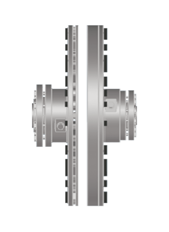
Non-contact drive technology improves equipment uptime by eliminating the mechanical wear mechanisms that cause the majority of unplanned failures in rotating equipment. Because torque is transmitted across an air gap using magnetic force rather than physical contact, there are no wear components, no lubrication requirements, and no alignment-induced forces propagating into bearings and seals.
This structural difference changes the reliability profile of an installation in several measurable ways:
- No coupling wear: Conventional couplings degrade over time through elastomer fatigue, gear tooth wear, or pin-and-bush erosion. Non-contact drives contain no consumable elements, so coupling-related failure events are removed from the maintenance schedule entirely.
- Misalignment tolerance: Non-contact drives accommodate significant radial and axial misalignment without transmitting force into connected equipment. Dynamic misalignment caused by thermal expansion, pipe strain, and foundation movement, which frequently exceeds installation tolerances during operation, no longer damages bearings and seals.
- Extended bearing and seal life: By removing coupling-induced peak loads, torsional oscillations, and vibration from the drivetrain, every downstream component operates under more stable load conditions. This extends the P-F curve, the time between detectable degradation and functional failure, giving maintenance teams more lead time to plan interventions rather than react to breakdowns.
- Fewer human-error events: Every maintenance intervention creates a probability of error. Eliminating scheduled coupling inspections, element replacements, and re-alignment procedures reduces the number of these events over an asset's life, which in turn reduces maintenance-induced failures.
- Soft-start and overload protection by design: Non-contact drives provide inherent soft-start capability and prevent overload propagation into the drivetrain during fault conditions, reducing the risk of cascading failures that cause extended downtime.
Zytec's non-contact drives, including the F-TORQ and A-TORQ, are engineered specifically for rotating equipment in asset-intensive industries where uptime is mission-critical. With a maintenance-free operational lifespan exceeding 20 years and documented energy savings of up to 50%, these drives address both the reliability and efficiency dimensions of equipment uptime in a single solution. If you want to understand how non-contact drive technology applies to your specific installation, contact Zytec directly to discuss your equipment profile and operational targets.
Frequently Asked Questions
How do I get started with tracking uptime if my facility doesn't have a CMMS or automated monitoring in place?
Start with a structured manual log that captures four data points for every event: the time the equipment stopped, the reason it stopped, the time it restarted, and who performed the intervention. Even a simple spreadsheet maintained consistently across shifts will give you enough data to calculate uptime percentages and identify your most frequent failure modes within a few months. Once you have that baseline, you can build a business case for investing in a CMMS or condition monitoring sensors by quantifying the actual cost of your current downtime events.
What's the difference between uptime and Overall Equipment Effectiveness (OEE), and which one should I be reporting to management?
Uptime (or availability) tells you how often equipment is running, but OEE tells you how well it's running when it is. A machine can have 97% uptime but still produce at reduced speed or generate excessive rejects, which OEE captures through its performance and quality factors. For management reporting, OEE is generally the more meaningful single metric for production environments because it reflects the full value of the asset, while uptime is more useful at the maintenance and reliability level where the focus is specifically on failure prevention and repair speed.
How do I know whether my low uptime is a maintenance problem or an engineering/design problem?
Look at your failure pattern rather than just the failure frequency. If the same component fails repeatedly on the same asset — for example, bearing failures recurring every few months on a specific pump — that points to a root cause engineering issue such as misalignment, overload, or an undersized component, not a maintenance execution problem. Maintenance problems tend to show up as inconsistent failure timing, errors shortly after interventions, or failures distributed randomly across similar assets. A root cause analysis (RCA) process, even an informal one using a fishbone diagram or 5-Why method, is the most reliable way to distinguish between the two.
Can high uptime actually mask equipment problems I should be paying attention to?
Yes, and this is one of the most important misconceptions to address. Equipment running continuously without triggering a shutdown can still be operating in a degraded state — elevated vibration, rising bearing temperatures, or increasing current draw may all be present without causing an immediate stop. Tracking uptime alone won't catch this; you need condition monitoring data trending alongside your uptime metrics. An asset that shows 98% uptime but is trending toward failure on vibration readings is not a healthy asset — it's a breakdown waiting to be scheduled.
How much does misalignment actually affect uptime in practice, and how often should shaft alignment be checked?
Misalignment is consistently identified as one of the leading root causes of premature bearing and seal failure in rotating equipment, with some industry estimates attributing up to 50% of rotating machinery failures to misalignment or its downstream effects. In practice, alignment should be verified at commissioning, after any maintenance that involves removing and reinstalling a machine, and periodically on critical assets — typically every 6 to 12 months depending on operating conditions. Thermal cycling, pipe strain, and foundation settling can all cause alignment to drift beyond acceptable tolerances even on equipment that was correctly aligned at installation.
What's a realistic timeline to see uptime improvements after implementing a predictive maintenance or condition monitoring program?
Most facilities begin to see measurable improvement within 6 to 12 months of consistently applying condition monitoring data to maintenance decisions — primarily because the program starts catching and correcting developing failures before they become unplanned shutdowns. The first few months are typically spent establishing baselines and learning what normal looks like for each asset, so early wins often come from identifying assets that were already in a degraded state. Significant, sustained uptime improvement — the kind that shows up in annual reliability metrics — generally requires 12 to 24 months of consistent data collection and program discipline.
If I install non-contact drive technology on critical equipment, do I still need to maintain a regular alignment and inspection schedule for those assets?
The inspection and re-alignment requirements specific to the coupling itself are eliminated, since there are no contact elements to wear, no elastomers to fatigue, and no alignment-sensitive force transmission to manage. However, you should still monitor the overall health of the connected equipment — the motor, bearings, seals, and driven machine — through vibration analysis and temperature trending, since those components can still degrade from causes unrelated to the drive. The key practical benefit is that you're removing one of the most frequent intervention triggers from your maintenance calendar, which both reduces labor costs and eliminates the risk of maintenance-induced failures associated with coupling work.