Identify the root cause of power quality issues
Before spending money on filters, capacitor banks, or new equipment, you need to understand exactly what type of power quality problem you are dealing with. Power quality is an umbrella term that covers several distinct phenomena, and the corrective action for one does not necessarily help with another.
The most common categories of industrial power quality issues include:
- Harmonic distortion: Non-linear loads such as variable frequency drives (VFDs), rectifiers, and switch-mode power supplies inject current harmonics back into the supply network, distorting the voltage waveform and causing overheating in transformers, cables, and motors.
- Poor power factor: Inductive loads such as motors and transformers draw reactive current that does not perform useful work, increasing apparent power demand and triggering reactive power surcharges from utilities.
- Voltage fluctuations and sags: Large motor starts, variable loads, and weak grid connections cause transient voltage drops that affect sensitive equipment and can cause contactors or drives to drop out.
- Voltage unbalance: Unequal loading across phases or supply asymmetry causes unbalanced three-phase voltages, which significantly increases motor heating and reduces efficiency.
Install a power quality analyser at your main distribution board and at key sub-distribution panels. Log data continuously for a minimum of seven days to capture full operating cycles, including startup sequences, shift changes, and peak load periods. Look for Total Harmonic Distortion (THD) levels above 5% on voltage or above 8% on current, power factor below 0.90, voltage unbalance exceeding 1%, and recurring voltage sags below 95% of nominal. These thresholds will guide the steps that follow.
Audit your rotating equipment and mechanical loads
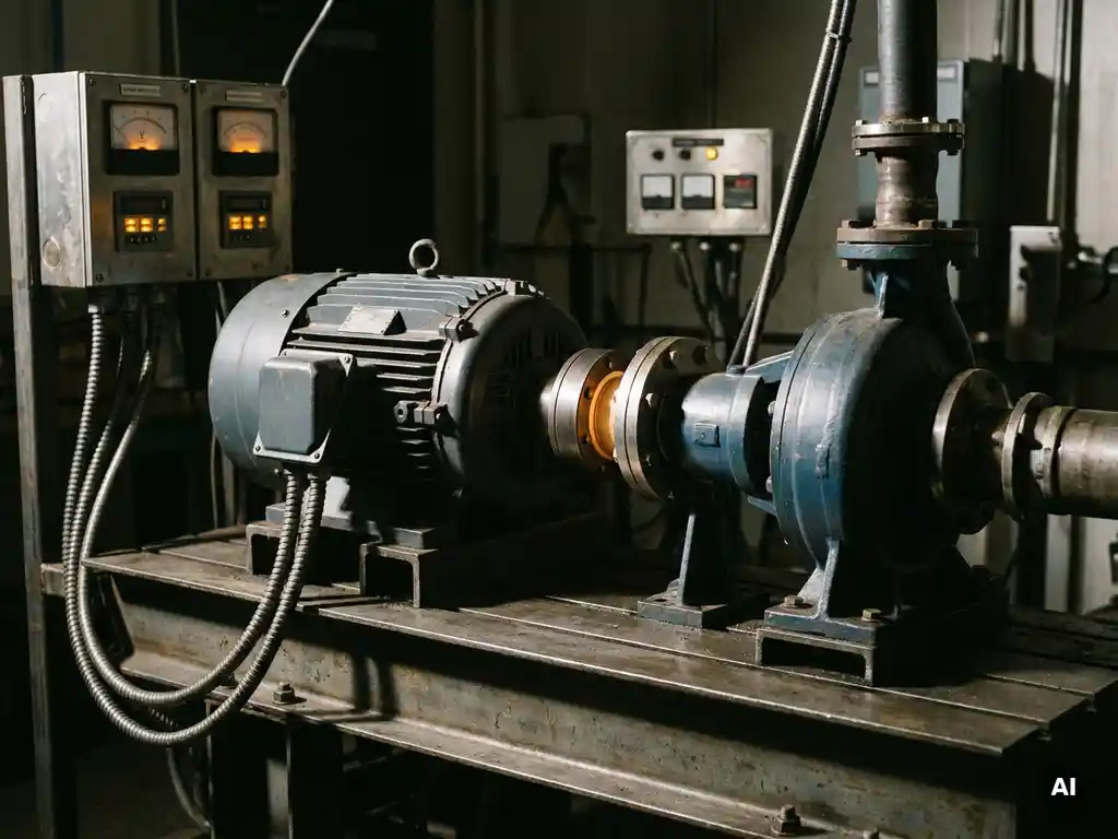
Rotating equipment is the dominant source of power quality disturbances in most industrial plants. Motors, pumps, fans, compressors, and conveyors together account for the majority of electrical load, and the way they are controlled, started, and mechanically coupled directly shapes the quality of power drawn from the network.
Conduct a systematic audit of every significant rotating load in your plant. For each piece of equipment, record the following:
- Motor rated power and actual operating load (measure shaft power or current draw under representative operating conditions)
- Control method: direct-on-line, soft starter, or variable frequency drive
- Coupling type between motor and driven machine
- Observed symptoms: vibration levels, bearing temperatures, unusual noise, tripping history
- Operating profile: hours per day at full load, partial load, and standby
Pay particular attention to equipment running significantly below its rated capacity. A pump or fan operating at 50% load on a fixed-speed motor is a common source of both energy waste and mechanical stress that feeds back into power quality. Also note which loads are controlled by VFDs, as these are typically the primary contributors to harmonic distortion and require specific attention in the next steps. After completing your audit, you will have a prioritised list of loads that are most likely driving your power quality problems.
Reduce harmonic distortion at the source
With your audit data in hand, focus first on reducing harmonic distortion at its origin. Treating harmonics at the source is always more effective than attempting to filter them after they have already propagated through the network.
VFDs are typically the largest harmonic contributors in industrial plants. Standard six-pulse VFDs draw current in characteristic pulses that generate significant 5th and 7th harmonic components. The following measures reduce harmonic injection at the drive level:
- Install line reactors or DC chokes on existing six-pulse drives. These are cost-effective and reduce current THD by roughly 30 to 50% compared to an unfiltered drive.
- Upgrade to 12-pulse or 18-pulse drive configurations for large drives above 75 kW where harmonic contribution is proportionally high.
- Specify active front-end (AFE) drives for new installations. AFE drives maintain near-unity power factor and produce very low harmonic distortion at the cost of higher initial investment.
- Install passive or active harmonic filters at the point of common coupling for groups of smaller drives where individual mitigation is not practical.
It is worth noting that harmonic filters add their own losses to the system. Passive harmonic filters introduce losses in the range of 0.7 to 2.0% of motor rated power, and active filters in the range of 1.0 to 3.0%. These losses are real parasitic costs that should be factored into your total system efficiency calculation. After implementing source-level harmonic mitigation, recheck THD at your measurement points to verify that levels have dropped within acceptable limits before moving on.
Correct power factor across critical installations
Once harmonic distortion is under control, address power factor. Poor power factor increases the current flowing through your cables, switchgear, and transformers without delivering additional useful work. This raises infrastructure losses, reduces available capacity, and typically results in reactive power penalty charges on your electricity bill.
Identify the installations with the lowest measured power factor from your audit data. For most plants, large induction motors running at partial load are the primary culprits, as motor power factor drops sharply below approximately 50% of rated load.
- Calculate the reactive power compensation required to bring each installation to a target power factor of 0.95 or above. Most utility tariffs eliminate reactive power charges above this threshold.
- Install fixed capacitor banks at motor control centres serving large, continuously running loads with stable reactive demand.
- Install automatic power factor correction (APFC) systems at main distribution boards for plants with variable load profiles. APFC panels switch capacitor steps in and out automatically to track changing reactive demand.
- Avoid installing capacitor banks on circuits with significant harmonic distortion without first adding detuning reactors. Capacitors resonate with harmonic currents and can be destroyed rapidly if harmonics are not addressed first.
Verify power factor correction by comparing measured power factor at the metering point before and after installation. A correctly sized and functioning correction system should bring site power factor consistently above 0.95 during normal operating hours. If power factor remains low despite correction, check for capacitor bank faults, blown fuses, or contactor failures within the APFC panel.
Decouple motor and load to stabilize power draw
One power quality improvement strategy that is frequently overlooked is addressing the mechanical interface between the motor and its driven machine. Mechanical coupling problems, including misalignment, torsional oscillation, and rigid load coupling, create fluctuating torque demands that translate directly into unstable current draw and voltage disturbances on the network.
When a motor and its driven load are rigidly or imperfectly coupled, every mechanical irregularity in the driven machine, such as impeller imbalance, pipe strain, or thermal expansion offset, generates torque spikes that appear as current fluctuations. In plants with many such loads operating simultaneously, the cumulative effect on supply voltage stability is measurable.
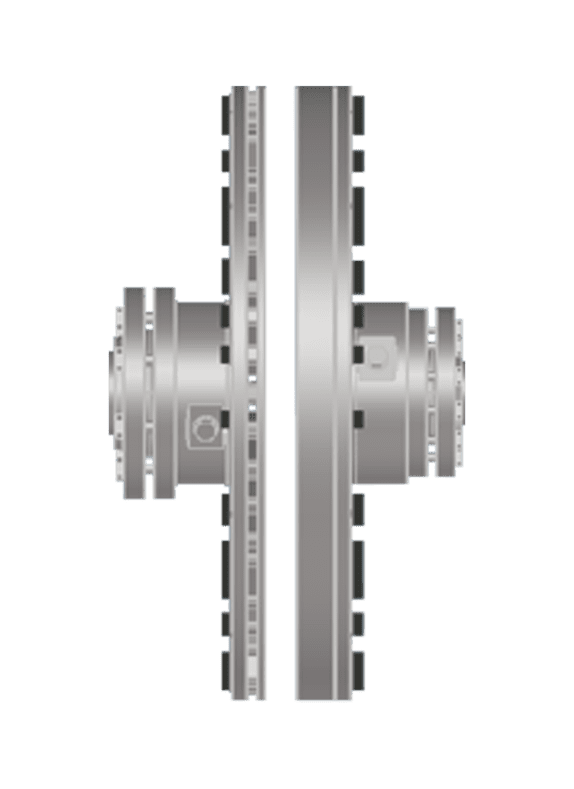
Non-contact magnetic drives address this at the source by transmitting torque across an air gap using permanent magnets, with no physical contact between the motor and the driven shaft. This eliminates the mechanical pathway through which torsional disturbances propagate. The result is a smoother, more stable current draw from the motor, reduced vibration in the drivetrain, and lower mechanical stress on bearings and seals. For variable-speed applications, a non-contact drive with a Motor Sliding Base (MSB) provides continuous speed adjustment without the harmonic injection associated with electronic VFDs, making it a particularly effective option in environments where power quality and hazardous area compliance are both concerns.
Review the results of your rotating equipment audit and identify loads where vibration levels are elevated, bearing temperatures are high, or current draw is noticeably unstable. These are candidates for mechanical decoupling as part of your power quality improvement programme. Correcting the mechanical root cause often reduces current fluctuation and the associated network disturbances more effectively than adding electrical mitigation alone.
Validate improvements and monitor power quality over time
After implementing corrective measures, systematic validation is essential. Power quality improvements that look good at the point of installation can degrade over time as loads change, equipment ages, or new sources of disturbance are introduced. Building a monitoring habit into your maintenance programme protects the investment you have made in correction.
Carry out a structured post-implementation measurement campaign using the same analyser and measurement points used in your initial audit. Compare the following metrics against your baseline readings:
- Voltage THD at main and sub-distribution boards (target: below 5%)
- Current THD at major drive installations (target: below 8%)
- Site power factor at the metering point (target: above 0.95)
- Voltage unbalance across phases (target: below 1%)
- Frequency and severity of voltage sags during motor starts
Document the results formally and compare them against your pre-improvement baseline. If any parameter has not improved as expected, trace back through the relevant step in this guide to identify where the correction is incomplete or where a new disturbance source has appeared.
For ongoing monitoring, consider installing permanent power quality meters at your main incoming supply and at key process areas. Modern power quality meters log continuously, generate alerts for threshold breaches, and integrate with plant SCADA or energy management systems. Reviewing power quality data quarterly allows you to catch developing problems, such as capacitor bank degradation or a new harmonic source from recently installed equipment, before they cause production disruptions or equipment damage.
How Zytec helps with power quality problems in your plant
Zytec's non-contact drives offer a direct, mechanical approach to stabilizing power draw and reducing the disturbances that undermine plant power quality. Rather than adding electrical filters downstream, Zytec technology addresses the problem at the rotating equipment itself. Here is how Zytec's solutions contribute to each layer of a power quality improvement programme:
- Stable current draw: By transmitting torque across an air gap with no physical contact, Zytec non-contact drives eliminate torsional oscillations and mechanical irregularities that cause fluctuating motor current and voltage disturbances on the network.
- No harmonic injection: Unlike electronic VFDs, Zytec's mechanical variable-speed solution introduces no harmonic distortion into the supply network, making it particularly valuable in plants where THD is already close to acceptable limits.
- Vibration reduction up to 80%: Reduced mechanical vibration means fewer torque spikes, smoother motor loading, and a more stable electrical demand profile across the installation.
- Energy savings up to 50%: For pump and fan applications, matching speed to actual process demand through a non-contact variable-speed drive cuts energy consumption significantly, reducing total electrical load and the reactive power burden on the network.
- Maintenance-free operation: With no wear components, no lubrication, and no alignment requirements, Zytec drives remove a recurring source of mechanical disturbance that would otherwise feed back into power quality over time.
If your plant is dealing with persistent power quality issues linked to rotating equipment, Zytec's engineering team can help you identify where non-contact drive technology fits into your corrective action plan. Contact Zytec to discuss your specific application and find out how a non-contact drive can stabilize your power draw, reduce your energy costs, and improve long-term equipment reliability.
Frequently Asked Questions
How do I know whether my plant's power quality problems are severe enough to justify the cost of corrective action?
A useful starting point is to quantify the financial impact before committing to any capital expenditure. Add up your reactive power penalty charges from the last 12 months of utility bills, estimate the cost of unplanned downtime caused by nuisance tripping or motor failures, and factor in premature equipment replacement costs. In most industrial plants, even a modest reduction in reactive power charges and one or two fewer unplanned motor failures per year will recover the cost of a structured power quality improvement programme within 12 to 24 months. If your power quality analyser is showing THD above 8% on current, power factor below 0.90, or voltage unbalance above 1%, the case for corrective action is almost always financially sound.
What is the right order to tackle power quality issues if I have multiple problems happening at the same time?
Always address harmonic distortion before correcting power factor — this sequence is critical, not just a preference. Installing capacitor banks on a network with high harmonic distortion creates resonance conditions that can destroy the capacitors rapidly and make harmonic problems significantly worse. Once THD is within acceptable limits, add power factor correction with detuned reactors as an additional safeguard. Voltage unbalance should be investigated in parallel, as it is often resolved through load redistribution across phases rather than dedicated equipment. Voltage sags during motor starts can be addressed last, as soft starters or VFDs installed to reduce harmonics will typically reduce inrush current and sag severity at the same time.
Can I use a standard clamp meter to diagnose power quality problems, or do I need a dedicated power quality analyser?
A standard clamp meter is not sufficient for power quality diagnosis. It will give you a basic RMS current reading but cannot capture harmonic content, power factor, voltage sag events, or waveform distortion — all of which are essential for accurate diagnosis. You need a dedicated power quality analyser capable of logging THD, individual harmonic orders, power factor, voltage and current waveforms, and transient events over an extended period. Instruments from manufacturers such as Fluke, Hioki, or Chauvin Arnoux cover this capability at a range of price points, and many specialist contractors offer short-term rental or measurement-as-a-service if purchasing an analyser outright is not justified.
Our plant runs multiple VFDs of different sizes. Do we need to install harmonic mitigation on every single drive, or can we use a centralised filter approach?
For large drives above roughly 75 kW, individual mitigation at the drive level — such as line reactors, DC chokes, or 12-pulse configurations — is generally more cost-effective and provides better harmonic control. For clusters of smaller drives below 30 kW, a single active harmonic filter installed at the point of common coupling serving that group is often more economical than fitting individual mitigation to each drive. A hybrid approach is common in practice: individual line reactors on all drives as a baseline measure, with a centralised active filter handling the residual harmonic content that individual reactors cannot eliminate. Your power quality audit data will show which areas of the plant have the highest harmonic contribution and should guide where centralised filtering gives the best return.
How do non-contact magnetic drives compare to VFDs for variable-speed control in terms of energy savings?
Both technologies follow the affinity laws for pumps and fans, meaning that reducing speed by 20% cuts power consumption by roughly 50% in theory. In practice, the energy savings from a non-contact magnetic drive are comparable to a VFD for many pump and fan applications, with the important distinction that a non-contact drive introduces no harmonic distortion and requires no power electronics to maintain. VFDs add conversion losses of approximately 2 to 5% and generate harmonics that require mitigation, whereas a non-contact drive has no conversion losses and no harmonic injection. For applications in hazardous areas, corrosive environments, or plants where THD is already near its limit, a non-contact drive often delivers equivalent energy savings with a significantly simpler overall system.
What are the most common mistakes plants make when installing power factor correction capacitor banks?
The most damaging mistake is installing capacitor banks without first addressing harmonic distortion, which leads to resonance, capacitor failure, and sometimes switchgear damage. The second most common error is oversizing the capacitor bank, which causes leading power factor during light load periods and can create overvoltage conditions that damage sensitive equipment. A third frequent issue is installing fixed capacitor banks on loads with highly variable reactive demand, where an automatic power factor correction panel with switched steps would be more appropriate. Always commission capacitor bank installations with a power quality analyser connected at the metering point to confirm that power factor has improved as expected and that no resonance conditions have developed.
How often should we re-audit power quality after the initial corrective measures have been implemented?
Conduct a full structured measurement campaign immediately after implementation to establish a corrected baseline, then schedule a repeat audit annually or whenever significant changes are made to the plant — such as adding new drives, replacing major motors, or reconfiguring distribution. In between formal audits, permanent power quality meters at the main incoming supply and key sub-distribution boards provide continuous visibility and will flag developing issues such as capacitor bank degradation or new harmonic sources from recently installed equipment. Reviewing logged data quarterly as part of your energy management routine is sufficient to catch most problems before they escalate into equipment damage or production disruptions.