Tools and checks needed before installation
Before any coupling touches a shaft, a proper pre-installation check eliminates the conditions that cause mounting-related damage from the start. Skipping this phase is where most coupling failures originate. Arriving at the job with the wrong tools or failing to inspect components before assembly means problems are built into the installation before the motor is ever switched on.
Gather the following tools and materials before beginning:
- Dial indicator or dial test indicator (DTI) with magnetic base
- Laser alignment system or precision straightedge
- Feeler gauges for axial gap measurement
- Torque wrench calibrated to the manufacturer's specification
- Shaft micrometer and bore gauge for interference fit verification
- Coupling hub puller (for removal of existing components)
- Cleaning solvents and lint-free cloths
- Anti-seize compound or specified lubricant for fasteners
- Manufacturer's installation drawing and torque specification sheet
With tools assembled, inspect every component before mounting. Check the coupling bore and shaft for burrs, scoring, or corrosion, and remove any surface defects with a fine file or emery cloth. Verify that the bore diameter matches the shaft diameter within the tolerance specified on the manufacturer's drawing. A bore that is too tight will stress the hub during installation; one that is too loose will allow fretting and relative movement under load. Inspect elastomeric elements, spider inserts, or flexible discs for cracks, deformation, or chemical degradation. Replace any element that shows visible wear before proceeding.
Align shafts correctly before mounting the coupling
Shaft alignment is the single most critical factor in preventing coupling misalignment and the cascade of bearing, seal, and shaft failures that follow from it. Industry experience consistently identifies misalignment as responsible for a significant share of rotating machinery failures, making this step non-negotiable regardless of how robust the coupling type appears to be. Alignment must be completed before the coupling hubs are fully secured.
Follow these steps in sequence:
- Perform a soft-foot check before any alignment measurement. Place a dial indicator on the motor foot and loosen each foot bolt individually. Any reading above 0.05 mm indicates soft foot, which must be corrected with precision shims before proceeding. Attempting alignment on a motor with soft foot will produce results that shift once the bolts are re-tightened.
- Set up your laser alignment system or dial indicator brackets on both shafts. Rotate both shafts together through at least 180 degrees to capture angular and offset misalignment in both the vertical and horizontal planes.
- Correct vertical misalignment first by adding or removing shims under the motor feet. Work from the rear feet to the front feet to avoid introducing new angular error as you correct offset.
- Correct horizontal misalignment by shifting the motor laterally. Use jack bolts where available to make fine adjustments without losing control of the motor position.
- Re-check alignment after tightening each set of foot bolts, as tightening frequently introduces small positional changes. Repeat the measure-correct-verify cycle until readings are within the coupling manufacturer's published tolerance.
After completing alignment, document the final readings before installing the coupling element. This gives you a verified baseline to compare against future alignment checks. Remember that thermal growth during operation will shift alignment from the cold-installed position. For equipment that runs hot, consult the manufacturer's guidance on pre-setting a thermal offset to compensate for predictable growth at operating temperature.
Mount the coupling using the right technique
Correct mounting technique prevents the two most common sources of installation-induced coupling damage: hub damage from improper fitting and element damage from incorrect assembly sequence. The method you use to seat the hub onto the shaft determines whether the coupling runs true or introduces immediate runout and stress into the drivetrain.
Fitting the hub to the shaft
For interference fit hubs, never use a hammer or direct impact to drive the hub onto the shaft. Impact loading bends the shaft, damages the hub bore, and introduces runout that no amount of subsequent alignment will correct. Instead, use one of the following controlled methods:
- Hydraulic hub installation tool: apply steady axial force through the tool until the hub reaches the specified position on the shaft. Monitor position against the manufacturer's reference mark.
- Thermal expansion method: heat the hub uniformly in an oven to the temperature specified by the manufacturer (typically 80 to 120 degrees Celsius for most steel hubs). Never use an open flame, as uneven heating creates stress gradients in the hub material. Slide the heated hub onto the shaft quickly and hold it in position until it cools and grips.
- For clearance or transition fit hubs with keyways: clean both the keyway and the key, verify that the key fits the slot without rocking, and seat the hub by hand or with light mallet pressure applied through a soft-faced drift, never directly against the hub face.
Once the hub is seated, verify its axial position against the manufacturer's drawing. Check runout using a dial indicator against the hub face and outside diameter. Acceptable runout limits vary by coupling type and speed, but most manufacturers specify less than 0.05 mm total indicated runout (TIR) at the hub face for standard industrial couplings. If runout exceeds the limit, the hub must be removed and the shaft and bore re-inspected before re-mounting.
Assembling the coupling element
Install the flexible element, grid, disc pack, or spider insert according to the manufacturer's assembly sequence. For jaw couplings, confirm that the spider is seated fully in both hubs before bringing the hubs together. For disc couplings, torque the disc pack bolts in a star pattern to the specified value, not sequentially around the bolt circle, to ensure even clamping. For gear couplings, apply the specified lubricant to the gear teeth before assembly and verify that the sleeve engages the full tooth width on both hubs.
Tighten all fasteners to the manufacturer's specified torque using a calibrated torque wrench. Never estimate fastener torque by feel. Under-torqued fasteners back out under vibration; over-torqued fasteners yield or strip threads, both of which compromise coupling integrity and create a maintenance hazard.
Verify installation with a post-mount inspection
A post-mount inspection confirms that the coupling has been installed correctly and that no errors were introduced during the assembly process. This step catches problems before the equipment is started, when correction is straightforward rather than urgent and disruptive.
- Re-check shaft alignment with the coupling element installed. Compare readings against the pre-installation baseline. If alignment has shifted by more than 0.02 mm, investigate the cause before starting the equipment. Common causes include coupling element pre-load pulling the shafts together, or fastener tightening shifting the motor position.
- Verify the air gap or axial spacing between coupling halves. Measure at multiple points around the circumference using feeler gauges. Variation greater than the manufacturer's tolerance indicates angular misalignment or a hub that is not running true.
- Confirm that all guards and protective covers are correctly fitted and secured before energizing the drive.
- Run the equipment briefly at no load and check for unusual vibration, noise, or heat at the coupling location. A correctly installed coupling on well-aligned shafts should produce no perceptible vibration and no audible noise beyond the normal mechanical tone of the drivetrain.
After the initial run, shut down the equipment and re-check fastener torque on the coupling bolts. Some coupling designs experience minor settling during the first operational cycle, which can reduce clamp load. A single re-torque after the first run is standard practice for critical installations and takes only minutes to complete.
Spot early warning signs of mounting-related damage
Even when installation is performed carefully, early detection of problems prevents minor issues from developing into major failures. Knowing what to look for during routine inspections allows maintenance teams to intervene before coupling failure causes broader drivetrain damage or unplanned downtime.
Watch for the following indicators during regular equipment checks:
- Increased vibration levels: A rise in overall vibration, particularly at frequencies corresponding to running speed or twice running speed, often indicates progressive misalignment or coupling element wear. Trending vibration data over time makes it possible to distinguish a coupling problem from other sources.
- Abnormal heat at the coupling: Couplings that run hot are transmitting friction or are under abnormal load. For elastomeric couplings, elevated temperature accelerates rubber degradation and shortens element life significantly.
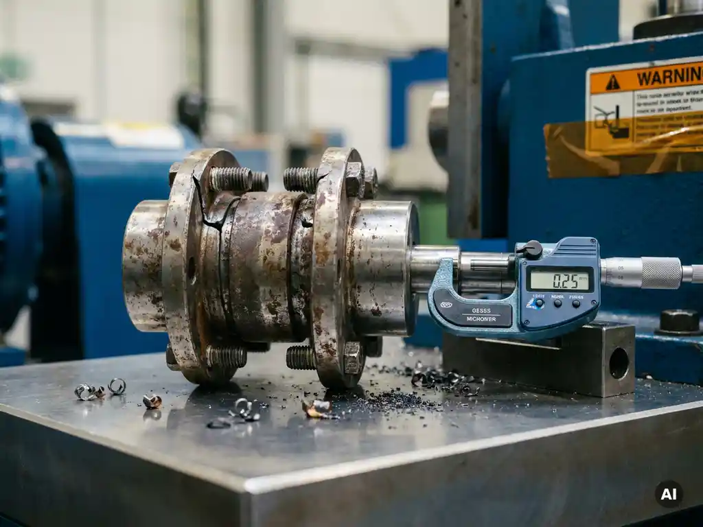
- Visible wear debris or rubber dust: Accumulation of black rubber dust around a jaw or tyre coupling indicates that the flexible element is wearing rapidly, typically due to misalignment or overload. This debris is a direct indicator of impending element failure.
- Lubricant leakage from gear or grid couplings: Leakage from the coupling sleeve indicates seal failure, which in turn allows lubricant contamination and accelerated gear tooth wear.
- Accelerated bearing wear on motor or driven equipment: Bearings that fail consistently before their expected service life are often being overloaded by misalignment forces transmitted through the coupling. The coupling appears intact while the bearings absorb the damage.
- Unusual noise: Clicking, rattling, or periodic thumping from the coupling area are characteristic of loose fasteners, worn elements, or excessive backlash in gear couplings.
When any of these signs appear, schedule an inspection at the next available opportunity rather than waiting for the next planned maintenance interval. Coupling-related failures rarely resolve themselves and typically escalate quickly once the flexible element or lubrication system is compromised.
When to consider a non-contact drive as an alternative
For installations where misalignment is difficult to control permanently, where maintenance access is limited, or where coupling-related failures recur despite correct installation practice, a fundamentally different approach may be worth evaluating. Conventional mechanical couplings, regardless of type, retain physical contact between driving and driven components and therefore continue transmitting misalignment forces into bearings and seals during operation, even when installed correctly.
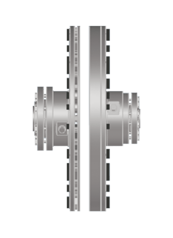
A non-contact drive eliminates this failure pathway entirely. Rather than accommodating misalignment through flexible elements that wear, it transmits torque across an air gap using magnetic coupling, so misalignment forces are never introduced into the drivetrain in the first place. There are no elastomers, no lubrication requirements, no wear components, and no periodic element replacement. The coupling inspection interval for conventional technologies ranges from monthly to annually; a non-contact coupling requires no scheduled coupling inspection at all.
This approach is particularly relevant for applications where dynamic misalignment during operation, caused by thermal expansion, pipe strain, or foundation movement, consistently exceeds what installation alignment can compensate for. It is also worth considering in high-inertia applications, ATEX hazardous area installations, or any situation where the total cost of coupling-related maintenance interventions represents a significant share of rotating equipment operating expenditure.
How Zytec helps prevent coupling damage
Zytec's non-contact drives offer a structural solution to the coupling damage and maintenance challenges described throughout this guide. Rather than improving on conventional coupling technology, Zytec eliminates the root causes of mounting-related failure by removing physical contact from the drivetrain entirely.
Here is what that means in practice for industrial operations:
- No laser alignment required: The F-TORQ Non-Contact Coupling accepts up to 12 mm of radial misalignment and 11 mm of axial misalignment, meaning installation can be completed without precision alignment equipment and without the risk of alignment-induced bearing overload during operation.
- No wear components: With no elastomers, no lubrication systems, and no friction elements, there is nothing to replace, re-torque, or inspect on a scheduled basis. Expected coupling service life covers the full lifetime of the installation.
- No overload propagation: Because torque is transmitted across an air gap, shock loads and torsional peaks cannot generate mechanical stress within the coupling or propagate into the motor and driven equipment.
- Reduced maintenance exposure: Fewer interventions near rotating equipment mean fewer hours of personnel exposure, lower risk of maintenance-induced failures, and a structurally lower total cost of ownership compared to conventional coupling technologies.
- Direct retrofit compatibility: The F-TORQ is designed as a functional drop-in replacement for all conventional coupling types, reusing existing motor, cabling, and baseplate infrastructure.
If recurring coupling damage, misalignment-driven bearing failures, or high maintenance frequency are affecting your operations, Zytec's engineering team can assess your specific application and provide a concrete business case. Contact Zytec to discuss how non-contact drive technology can be applied to your rotating equipment.
Frequently Asked Questions
How often should I re-check shaft alignment after the initial installation?
Alignment should be verified at every planned maintenance interval, and additionally after any event that could disturb the drivetrain — including motor replacement, baseplate repairs, pipe work changes, or significant temperature fluctuations. For critical assets, a baseline alignment check within the first 500 operating hours after installation is strongly recommended, as thermal stabilisation and foundation settling can shift the cold-installed position meaningfully. Trending alignment readings over time is more valuable than any single measurement, as it reveals whether deterioration is progressive or event-driven.
What is the most common mistake made when replacing a failed coupling rather than installing a new one?
The most common mistake is replacing the coupling element without investigating why it failed in the first place. If the root cause — typically misalignment, soft foot, or an incorrect coupling selection — is not corrected before the new element is installed, the replacement will fail on a similar timeline. Always treat a coupling failure as a diagnostic event: inspect the wear pattern on the failed element, check current alignment readings, and verify that the replacement coupling is correctly rated for the actual torque and speed of the application before proceeding.
Can I use the same alignment tolerances for all coupling types, or do they vary?
Tolerances vary significantly by coupling type and must always be taken from the specific manufacturer's documentation for the coupling being installed — not from a generic industry table. Gear couplings, disc couplings, jaw couplings, and tyre couplings each have different angular and parallel offset limits, and those limits also change with operating speed. Running a coupling beyond its published misalignment tolerance, even slightly, accelerates wear on the flexible element and increases the radial load transmitted to adjacent bearings.
What should I do if I don't have access to a laser alignment system — is a dial indicator sufficient?
A dial indicator setup is a valid and proven method when used correctly, and it remains widely used in facilities that do not have laser systems available. The key is rigorous technique: bracket sag must be measured and compensated for, both shafts must be rotated together through the full measurement sweep, and readings must be taken in both the vertical and horizontal planes. The practical limitation of dial indicators is that they are more time-consuming and more susceptible to operator error than laser systems, so extra care in setup and a second verification pass are advisable, particularly on higher-speed or higher-criticality equipment.
How do I know if my coupling is the right size and type for the application, or if a previous installer selected the wrong one?
Start with the service factor: the coupling's rated torque capacity, after applying the manufacturer's service factor for your application type, must exceed the actual peak torque of the drive. Compare the existing coupling's nameplate data or part number against the driven equipment's torque and speed requirements, the degree of misalignment expected in service, and any environmental constraints such as temperature range or hazardous area classification. If that documentation is unavailable, a coupling manufacturer or distributor can perform an application review using motor nameplate data and basic equipment specifications — this is a routine service and typically free of charge.
Is it safe to operate equipment briefly if I suspect a coupling problem but cannot schedule an immediate shutdown?
This depends on the severity of the symptoms and the consequences of an uncontrolled failure. Visible rubber debris, significant heat, or audible impact noise indicate that element failure is imminent and continued operation risks secondary damage to bearings, seals, and shafts that will substantially increase repair cost and downtime. If shutdown is genuinely unavoidable, increase inspection frequency to multiple times per shift, remove any non-essential load from the drive, and have a replacement coupling ready to install at the first available opportunity. Never treat a deteriorating coupling as a stable condition — the failure mode is typically rapid once the flexible element or lubrication system is compromised.
At what point does it make financial sense to switch from a conventional coupling to a non-contact drive solution?
The business case becomes straightforward when you total the recurring costs of conventional coupling ownership: replacement elements, alignment labour, associated bearing and seal replacements, and the production value of unplanned downtime events. For assets that require coupling intervention more than once per year, or where a single unplanned failure event carries significant production or safety consequences, the total cost of ownership of a non-contact drive typically compares favourably within the first two to three years. Applications with persistent dynamic misalignment — caused by thermal growth, pipe strain, or foundation movement — are particularly strong candidates, because no amount of installation precision resolves a misalignment source that is inherent to the operating conditions.