Assess your equipment's vulnerability to ground movement
Before you can protect anything, you need to understand what is at risk. Ground movement affects different equipment types in different ways, and a structured vulnerability assessment gives you the information needed to prioritize action. Start with your rotating equipment, since pumps, fans, compressors, and generators are among the most sensitive assets on any industrial site.
- Map all rotating equipment on your site, noting shaft alignment tolerances, coupling types, and the age of each installation.
- Review foundation types for each asset, including whether equipment sits on concrete plinths, structural steel frames, or shared baseframes that span multiple machines.
- Check historical alignment records to identify machines that have required frequent realignment, as this is a strong indicator of ongoing foundation movement or pipe strain.
- Consult geological data for your site, including any known subsidence risk from groundwater extraction, mining activity, or soft soil layers beneath your facility.
- Identify which assets are in continuous-duty service or on critical production paths, since these carry the highest consequences of failure.
After completing this assessment, you should have a ranked list of vulnerable assets grouped by risk level. Equipment showing signs of recurring misalignment, installed on shallow foundations, or sitting on geologically unstable ground should move to the top of your protection priority list. This list becomes the working document for every step that follows.
Eliminate mechanical weak points in rotating equipment
With your vulnerability assessment complete, the next step is to address the mechanical weak points that make equipment susceptible to vibration-related failures during seismic activity or subsidence events. Traditional mechanical couplings, rigid pipework connections, and poorly maintained bearings all amplify the damage caused by ground movement rather than absorbing it.
Review coupling condition and type
Inspect all coupling elements on your priority asset list. Jaw couplings, pin-and-bush couplings, and gear couplings all rely on mechanical contact to transmit torque, which means any ground-induced misalignment creates immediate mechanical stress. Elastomeric elements degrade over time, reducing their ability to absorb shock. Check for wear, cracking, hardening, or deformation in any flexible element, and replace worn components before a ground movement event pushes them beyond their tolerance limits.
Address pipe strain and structural rigidity
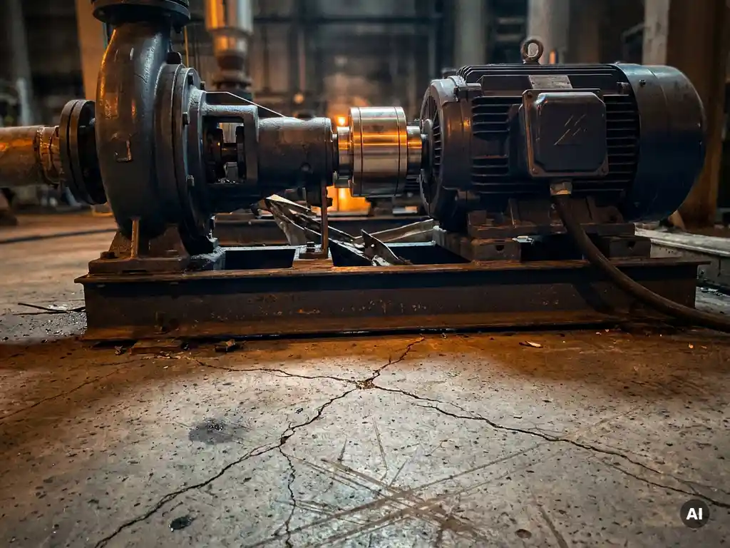
Rigid pipework connected directly to pump flanges is one of the most common sources of induced misalignment, and it becomes far more damaging when the ground shifts. Install flexible pipe connections or expansion joints on suction and discharge lines wherever fixed pipework meets rotating equipment. Confirm that pipe supports are not transferring load into the machine casing. A pipe that is pulling or pushing on a pump nozzle before a seismic event will cause immediate seal and bearing damage the moment the ground moves.
After addressing couplings and pipework, verify alignment on all priority assets and document the baseline readings. This gives you a reference point for post-event inspection and helps you detect foundation movement over time by comparing readings at regular intervals.
Install non-contact magnetic drives to absorb misalignment
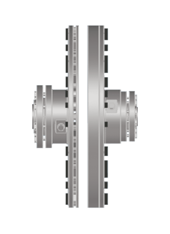
The most effective structural upgrade you can make to protect rotating equipment from earthquake damage and subsidence is replacing conventional contact couplings with non-contact magnetic drives. Unlike mechanical couplings, which transmit torque through physical engagement, magnetic drives transmit power across an air gap using permanent magnets. This means misalignment, whether caused by ground movement, thermal expansion, or pipe strain, does not generate mechanical stress in the drivetrain.
The engineering principle matters here. A conventional coupling has radial stiffness that reacts against misalignment, transmitting those forces directly into motor bearings, driven-equipment bearings, and seals. A non-contact magnetic drive has a radial stiffness of zero and a torsional stiffness of zero, meaning misalignment forces are not propagated into connected components at all. In practical terms, this means bearings and seals continue operating under stable load conditions even when the foundation has shifted.
- Select a non-contact magnetic drive rated for your motor power and speed from the manufacturer's catalogue tables, which cover IEC 50 Hz and NEMA 60 Hz motors from 7.5 kW to over 1,600 kW.
- Confirm the air gap specification for your chosen unit. Non-contact drives can accommodate static radial misalignment up to 12 mm and axial misalignment up to 11 mm, which covers the movement range of most subsidence and seismic events in industrial settings.
- Remove the existing coupling and install the magnetic drive using slip-fit or shrink-disc hub mounting. No laser alignment is required during installation, which simplifies the process and reduces installation time.
- Set the air gap to the specified range using simple visual gauging. There is no need for precision shimming or soft-foot correction procedures.
- Confirm that the existing motor and cabling can be reused. Non-contact drives are designed as functional drop-in retrofits that do not require motor replacement or cabling upgrades.
Once installed, verify that the drive runs smoothly at operating speed and that no unusual vibration is present. Monitor air gap dimensions during the first weeks of operation. If the gap begins to change, this serves as an early warning indicator of bearing degradation or ongoing foundation movement, giving you advance notice before any failure occurs. This predictive function is one of the practical advantages of non-contact technology in environments where ground movement is an ongoing concern.
Protect ancillary systems from secondary vibration damage
Rotating equipment is the primary concern, but seismic and subsidence events generate vibration that propagates through structural steelwork, pipework, and cable trays to affect ancillary systems. Control panels, instrumentation, junction boxes, and motor control centres are all vulnerable to vibration-induced damage, including loose terminal connections, relay chatter, and component fatigue.
- Inspect all cable tray supports and conduit fixings near rotating equipment. Ensure they have sufficient flexibility to accommodate differential movement between the structure and the equipment.
- Check terminal connections in control panels and junction boxes on a scheduled basis, especially in facilities located in areas with known seismic activity or active subsidence. Loose terminals cause intermittent faults that are difficult to diagnose and can trigger spurious shutdowns.
- Install vibration-isolating mounts under control panels and instrumentation enclosures that are floor-mounted near heavy rotating equipment.
- Review the fixings on pressure transmitters, flow meters, and temperature sensors installed on pipework connected to rotating equipment. Threaded connections can loosen progressively under cyclic vibration.
Secondary vibration damage is often overlooked because it tends to appear gradually, presenting as intermittent faults or unexplained instrument drift rather than obvious physical damage. Addressing it proactively, particularly on assets that have already been upgraded with improved coupling technology, ensures that your mechanical improvements are not undermined by electrical or instrumentation failures downstream.
Verify equipment integrity after a seismic or subsidence event
After any ground movement event, whether a measurable earthquake, a confirmed subsidence episode, or even an unusually severe vibration event from nearby construction or blasting, a structured post-event inspection is essential. Do not assume that equipment that continues running is undamaged. Internal damage to bearings, seals, and alignment can develop silently and lead to failure days or weeks later.
Immediate post-event checks
Conduct a visual walkthrough of all rotating equipment within the first hour following a ground movement event. Look for visible misalignment between the motor and driven equipment, unusual noise or vibration at operating speed, fluid leaks from seals or gland packings, and any visible cracking in foundation plinths, grout, or structural supports. Shut down any machine showing signs of acute distress and lock it out before closer inspection.
Detailed alignment and condition verification
- Re-check shaft alignment on all conventional-coupling installations and compare readings against your pre-event baseline. A shift greater than the coupling's rated tolerance requires corrective action before restarting.
- For assets fitted with non-contact magnetic drives, measure the air gap dimension and compare it against the installation record. A change in air gap indicates that the foundation or connected pipework has moved, even if the machine is still running within tolerance.
- Take vibration readings on all priority assets and compare against baseline spectra. New frequency components or elevated overall vibration levels indicate internal damage.
- Inspect flexible pipe connections and expansion joints for deformation, cracking, or displacement.
- Check all terminal connections in control panels and junction boxes for looseness.
Document all findings systematically and update your asset records. Even if no immediate corrective action is required, a pattern of small shifts across multiple events gives you valuable data for foundation condition monitoring and long-term resilience planning.
Build a long-term resilience plan for asset-intensive sites
Protecting industrial equipment from seismic and subsidence damage is not a one-time project. Ground movement is often a recurring phenomenon, particularly on sites affected by groundwater management, nearby infrastructure works, or geological conditions that cause gradual settlement over years. A long-term resilience plan ensures that your site continues to improve its ability to absorb and recover from ground movement events rather than simply reacting to each one.
- Establish a foundation monitoring programme using survey benchmarks or digital settlement monitoring systems. Quarterly readings on key equipment foundations allow you to detect and respond to subsidence trends before they cause equipment damage.
- Set alignment inspection intervals based on risk, with higher-risk assets inspected more frequently. For assets fitted with non-contact magnetic drives, air gap monitoring can replace conventional alignment checks and requires no shutdown time.
- Build a rolling upgrade programme to replace remaining conventional couplings on critical assets with non-contact alternatives as part of planned maintenance cycles, rather than waiting for failure-driven replacement.
- Include seismic and subsidence scenarios in your site risk register and maintenance strategy reviews, ensuring they are treated as engineering design inputs rather than insurance considerations.
- Train maintenance teams to recognise the early signs of foundation movement and vibration-induced damage, and establish clear escalation procedures for post-event inspections.
A resilience plan grounded in these principles reduces your total cost of ownership over time by shifting the site from reactive to proactive asset management. The investment in better coupling technology, structured monitoring, and trained personnel pays back through fewer unplanned shutdowns, lower repair costs, and longer asset service life.
How Zytec helps protect industrial equipment from ground movement
Zytec's non-contact magnetic drives are specifically engineered to address the mechanical vulnerabilities that make rotating equipment susceptible to earthquake damage and subsidence damage. Where conventional couplings transmit misalignment forces directly into bearings and seals, Zytec's technology eliminates that force transfer entirely by operating across a magnetic air gap with zero radial and zero torsional stiffness.
The practical benefits for sites exposed to ground movement are concrete and measurable:
- Up to 12 mm radial and 11 mm axial misalignment capacity, covering the movement range of most seismic and subsidence events without mechanical stress in the drivetrain
- No wear components, no lubrication, and no scheduled coupling maintenance, reducing human intervention near rotating equipment and lowering the risk of maintenance-induced failures
- Air gap monitoring as a built-in condition indicator, giving early warning of foundation movement or bearing degradation without requiring shutdown or specialist instruments
- Vibration reduction up to 80%, protecting downstream components including bearings, seals, gearboxes, and structural interfaces
- Drop-in retrofit compatibility with all conventional coupling types, reusing existing motors and cabling for straightforward installation during planned maintenance windows
- Rated service life exceeding 20 years with no coupling element replacement, supporting long-term resilience planning and ISO 55000 asset management objectives
If your site faces ongoing subsidence risk, operates in a seismically active region, or has rotating equipment with a history of recurring alignment issues, Zytec's engineering team can assess your installation and recommend the right solution from the F-TORQ, A-TORQ, or V-TORQ product range. Contact Zytec to discuss your specific application and find out how non-contact drive technology can become the foundation of your equipment resilience strategy.
Frequently Asked Questions
How do I know if my site's ground movement risk is serious enough to justify upgrading to non-contact magnetic drives?
If your maintenance records show recurring shaft misalignment on the same machines, unexplained bearing or seal failures, or if your site sits on ground affected by groundwater extraction, mining activity, or soft soil layers, the risk is already materialising — you may just not be attributing it to ground movement. A practical first step is to pull alignment history for your critical rotating assets over the past two to three years. If any machine has required realignment more than once per year without a clear mechanical cause, foundation movement is a likely contributor and the case for non-contact technology is strong.
Can non-contact magnetic drives be installed during a short planned maintenance window, or do they require extended downtime?
Zytec's magnetic drives are designed as drop-in retrofits that reuse your existing motor, shaft, and cabling, which keeps installation time comparable to a conventional coupling replacement. There is no requirement for precision laser alignment during fitting, no soft-foot correction procedure, and no need for specialist alignment contractors on-site. Most installations can be completed within a standard planned maintenance window, making them practical to roll out across a site as part of a phased upgrade programme rather than requiring a dedicated shutdown campaign.
What is the most common mistake industrial sites make when responding to a seismic or subsidence event?
The most damaging mistake is assuming that equipment which continues to run after a ground movement event is undamaged and needs no inspection. Bearings and seals can sustain internal damage that is not immediately detectable through noise or vibration but that progresses rapidly under continued operation, leading to failure days or weeks later. The structured post-event inspection process described in this guide — including air gap checks on magnetic drives, alignment verification on conventional couplings, and vibration baseline comparisons — exists specifically to catch this silent damage before it becomes a production-stopping failure.
How does air gap monitoring on a non-contact magnetic drive work as a condition indicator in practice?
When a Zytec magnetic drive is installed, the air gap dimension between the rotor and stator elements is recorded as a baseline. During routine walkdowns or scheduled inspections, a technician measures the current gap using simple visual gauging — no instruments or shutdown are required. If the gap has changed from the baseline, it indicates that either the foundation has shifted, connected pipework is exerting load on the machine, or bearing wear has allowed shaft movement. This gives maintenance teams an early, actionable warning that something has changed in the drivetrain or foundation before any failure symptom appears.
Are there equipment types or applications where non-contact magnetic drives are not suitable for seismic or subsidence protection?
Non-contact magnetic drives are rated from 7.5 kW to over 1,600 kW and cover the majority of rotating equipment found on industrial sites, including pumps, fans, compressors, and generators. They are not typically suited to applications requiring precise speed synchronisation, very high torque density in an extremely compact envelope, or operation in strong external magnetic fields that could interfere with the drive's permanent magnets. For applications at the boundaries of the standard range, Zytec's engineering team can assess the specific duty and advise whether a standard product or a modified configuration is appropriate.
How should we prioritise which assets to upgrade first if budget constraints mean we cannot replace all couplings at once?
Start with assets that combine high consequence of failure with existing evidence of foundation movement or recurring misalignment — these are the machines where a ground movement event is most likely to cause immediate, costly damage. Critical-path production equipment, continuous-duty assets with no installed standby, and machines with a history of bearing or seal failures should all sit at the top of the list. Assets on shared baseframes or connected to rigid pipework that cannot easily be modified are also high-priority candidates, since they have fewer alternative means of absorbing misalignment forces.
What should a foundation monitoring programme look like for a site with moderate subsidence risk?
For a site with moderate subsidence risk, a practical starting point is installing survey benchmarks at key equipment foundation corners and taking quarterly elevation readings using a digital level or total station. This allows you to track settlement trends across the site and identify foundations that are moving faster than others. Where the budget allows, wireless digital settlement sensors can automate this process and flag threshold exceedances in real time. The monitoring data should feed directly into your maintenance planning cycle, triggering alignment inspections or foundation remediation work when movement rates exceed agreed thresholds rather than waiting for equipment symptoms to appear.