Tools and checks needed before starting alignment
Before you touch any fasteners or adjustment screws, gather everything you need and confirm the machine is safe to work on. Starting without the right tools leads to incomplete corrections and wasted time. A lockout/tagout procedure must be completed before any work begins — no exceptions.
Collect the following tools and reference materials before you start:
- Laser alignment system or dial indicator set with magnetic bases
- Feeler gauges and a calibrated torque wrench
- Stainless steel shims in a range of thicknesses (0.05 mm to 2 mm)
- Soft foot measurement tool or dial indicator
- Straight edge and precision level
- Manufacturer alignment tolerances for the specific coupling type and speed
- Baseline vibration readings (from a handheld vibration meter or existing monitoring data)
Also confirm that the baseplate and foundation are in acceptable condition before you proceed. A cracked grout bed or a loose anchor bolt will undermine any alignment work you do. Check that all coupling guards are removed and that the coupling itself is in serviceable condition — worn elastomers or damaged coupling elements will introduce measurement error and should be replaced before alignment begins.
Identify the type and severity of misalignment
Misalignment on a pump or fan drivetrain takes two distinct forms, and you need to know which one you are dealing with before making any corrections. Treating angular misalignment with a parallel correction, or vice versa, will not solve the problem and may make it worse.
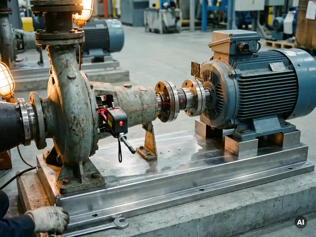
Use your laser alignment tool or dial indicators to take initial readings with the machine cold and stationary. Record the values without making any adjustments yet. This baseline tells you the full picture.
- Mount the measurement fixtures on both shafts according to your alignment tool's setup instructions. Ensure there is no axial float in either shaft before you zero the instruments.
- Rotate both shafts together through at least 180 degrees (ideally 360 degrees) and record the readings at the 12, 3, 6, and 9 o'clock positions.
- Identify whether the error is primarily parallel (offset) — where the shaft centerlines are parallel but displaced — or angular — where the centerlines meet at an angle — or a combination of both.
- Compare your readings against the manufacturer's published tolerance table for the coupling type and operating speed. Tighter tolerances apply at higher speeds.
After this step, you should have a clear numerical picture of how far out of tolerance the machine is and in which direction. Note whether the misalignment is in the vertical plane, the horizontal plane, or both. This determines the sequence and type of corrections you will make in the steps that follow.
Correct soft foot before adjusting alignment
Soft foot is a condition where one or more of the motor's feet do not sit flat against the baseplate, causing the frame to distort when the hold-down bolts are tightened. If you attempt shaft alignment correction without eliminating soft foot first, tightening the bolts will shift the shaft position and invalidate all your measurements. This is one of the most common reasons alignment jobs have to be repeated.
Check for soft foot with a dial indicator positioned on the motor housing, directly above each foot in turn. Loosen one foot bolt at a time while the other three remain tight, and observe the indicator reading. A movement of more than 0.05 mm indicates soft foot at that location.
- Identify which feet show movement above the acceptable threshold.
- Slide a feeler gauge under the affected foot to measure the gap precisely.
- Insert the correct shim thickness under that foot. Use the fewest shims possible — stacking many thin shims introduces its own instability.
- Re-tighten the bolt and re-check. Repeat until all four feet show less than 0.05 mm of movement when their bolt is loosened.
- Once all feet pass the soft foot check, re-tighten all hold-down bolts to the specified torque in a cross pattern.
With soft foot corrected, your alignment measurements will be stable and repeatable. Do not skip this step even if the machine appears to sit flat — angular soft foot caused by a bowed frame or a tapered shim from a previous job is not always visible to the eye.
Adjust shaft alignment to within tolerance
Now that soft foot is eliminated and you have a reliable baseline measurement, you can begin making the actual shaft alignment corrections. Work in the vertical plane first, then the horizontal plane. This sequence prevents corrections in one plane from disturbing corrections already made in the other.
Vertical correction
Vertical corrections are made by adding or removing shims under the motor feet. Your laser alignment tool or dial indicator calculations will tell you exactly how much shim to add or remove at the front feet and rear feet, respectively, to correct both parallel offset and angular error in the vertical plane simultaneously.
- Loosen all four motor hold-down bolts slightly — enough to allow the motor to lift but not enough to let it shift horizontally.
- Add or remove shims at the front and rear feet according to your calculated correction values.
- Re-tighten the bolts to the specified torque and re-take your alignment readings.
- Repeat until vertical plane readings are within the manufacturer's tolerance.
Horizontal correction
Horizontal corrections are made by sliding the motor sideways on the baseplate using the adjustment screws or jack bolts if fitted. Horizontal moves affect both parallel and angular error in the same way as vertical shim changes, but without the need to loosen all bolts simultaneously.
- Loosen the hold-down bolts just enough to allow lateral movement.
- Use the jack bolts or a soft-faced mallet to nudge the motor into position. Small movements have a large effect — work in increments of 0.1 mm or less when you are close to tolerance.
- Re-tighten the hold-down bolts and re-check the readings. Tightening the bolts often causes a small shift, so account for this in your final approach.
- Iterate until horizontal plane readings are within tolerance.
After both planes are within tolerance, perform a final full rotation check with all bolts at the correct torque. The readings should remain stable. If they shift significantly when the bolts are fully tightened, re-check for residual soft foot.
Verify alignment and run a post-correction check
A completed alignment correction is not finished until it is verified under operating conditions. Static cold alignment is a starting point — thermal growth during operation will shift the shaft positions, and the goal is for the machine to be within tolerance when running at normal operating temperature, not just when cold.
If your equipment operates at elevated temperatures or has significant thermal growth, apply the manufacturer's recommended thermal offset values before your final cold alignment check. This means intentionally setting the cold alignment slightly out of position so that thermal expansion brings it into tolerance at operating temperature.
- Reinstall the coupling and coupling guard before starting the machine.
- Run the equipment for at least 20 to 30 minutes to reach normal operating temperature.
- Shut down and lock out the machine, then re-check alignment while the machine is still warm.
- Compare the warm readings against the cold readings and against the manufacturer's running tolerances.
- Take a vibration reading at the bearing housings and compare against your pre-work baseline. A successful pump or fan misalignment fix should show a measurable reduction in vibration, particularly in the radial direction at 1x and 2x running speed.
If vibration remains elevated after a confirmed good alignment, investigate other potential sources: bearing condition, balance, resonance, or pipe strain on the pump casing. Pipe strain is a particularly common cause of recurring misalignment — if the pipework is pulling or pushing on the pump casing, the alignment will shift back within hours of startup.
Prevent recurring misalignment with long-term solutions
Fixing misalignment once is straightforward. Preventing it from coming back requires understanding why it occurred in the first place. Recurring shaft misalignment repair calls are a sign that something in the system is working against you — and finding that root cause is what separates a lasting fix from a temporary one.
Common root causes of recurring misalignment include:
- Pipe strain: Poorly supported or thermally constrained pipework exerts forces on the pump casing that distort alignment after startup. Check pipe support locations and expansion joints.
- Foundation movement: Settling grout, loose anchor bolts, or a structurally inadequate baseplate will allow the motor to drift over time. Re-grout or reinforce as needed.
- Thermal cycling: Equipment that heats and cools repeatedly will experience dynamic misalignment even if the cold alignment is perfect. Thermal offsets must be built into the cold alignment target.
- Inadequate coupling selection: A coupling with insufficient misalignment capacity will transmit corrective forces into the bearings rather than accommodating the deviation. Verify that the installed coupling is rated for the expected dynamic misalignment range.
Establishing a regular alignment check interval — typically every 6 to 12 months for critical rotating equipment — and logging the results over time will reveal trends before they become failures. Vibration monitoring between scheduled checks provides early warning of developing misalignment so you can intervene before bearing damage occurs.
How Zytec's non-contact drives eliminate misalignment at the source
The steps above describe best-practice shaft alignment procedure for conventional coupled drivetrains. They work, but they require skilled labour, precision instruments, and repeated interventions over the life of the equipment. For organizations looking to remove misalignment as a recurring maintenance driver entirely, Zytec offers a fundamentally different approach.
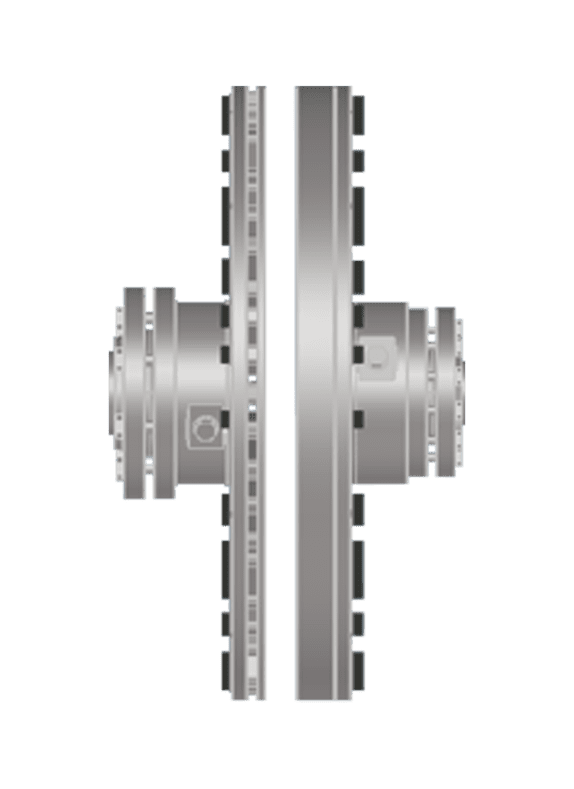
Zytec's non-contact magnetic drives transmit torque across an air gap without any physical contact between the motor and driven equipment. Because there is no mechanical connection, misalignment does not generate bearing loads, seal stress, or vibration. The result is a drivetrain that is structurally immune to the consequences of both static installation offset and dynamic operational misalignment caused by thermal expansion, pipe strain, and foundation movement.
Key advantages for pumps, fans, and other rotating equipment include:
- No laser alignment required during installation — static misalignment up to 12 mm radial is accommodated by design
- Dynamic operational misalignment introduces zero additional bearing or seal load
- No wear components, no lubrication, and no scheduled coupling inspection — maintenance-free service life of 20 years or more
- Vibration reduction up to 80% and energy savings up to 50% compared to conventional coupled installations
- Direct retrofit onto existing motors and cabling with no inverter-duty upgrades required
If misalignment is a recurring problem in your plant and you want to eliminate it rather than manage it, contact Zytec to discuss which non-contact drive is the right fit for your application.
Frequently Asked Questions
How do I know if my pump or fan is misaligned without laser alignment tools?
While a laser alignment system gives you the most accurate readings, early signs of misalignment can be detected through elevated vibration at 1x and 2x running speed, unusual heat at the bearing housings or coupling, premature seal or bearing failures, and visible wear patterns on coupling elastomers. A handheld vibration meter and an infrared thermometer are practical first-line diagnostic tools. That said, these indicators confirm a problem exists — they cannot replace precision measurement when it comes to making a verified correction.
What alignment tolerances should I be targeting for my specific application?
Alignment tolerances are not universal — they depend on the coupling type, shaft speed, and the equipment manufacturer's specifications. As a general rule, tighter tolerances apply at higher speeds: a machine running at 3,000 RPM requires significantly tighter alignment than one running at 750 RPM. Always refer to the coupling manufacturer's published tolerance table first, then cross-reference with the driven equipment manufacturer's recommendations. If neither is available, industry standards such as ISO 10816 or ANSI/HI guidelines for pumps provide a reliable baseline.
How often should I re-check shaft alignment after an initial correction?
For critical rotating equipment such as process pumps and large fans, a re-check within the first 200 to 500 operating hours after a new installation or major correction is strongly recommended — thermal settling, grout cure, and initial pipe strain effects tend to show up in this window. After that, a scheduled check every 6 to 12 months is appropriate for most applications, with vibration monitoring used between checks to catch developing issues early. Equipment subject to frequent thermal cycling, heavy pipe loads, or foundation movement may warrant a shorter interval.
Can I perform shaft alignment on a hot machine, or does it always have to be done cold?
Alignment measurements are always taken with the machine stationary for safety reasons, but the thermal state of the machine matters. A cold alignment reading does not reflect where the shafts will sit at normal operating temperature due to thermal growth. The correct approach is to apply the manufacturer's thermal offset values to your cold alignment target so that the machine lands within tolerance once it reaches operating temperature. If thermal offset data is not available, take a warm check shortly after shutdown (within 15 minutes) to measure the actual thermal shift and use that data to refine your cold target.
What is the most common mistake technicians make during a shaft alignment job?
Skipping or rushing the soft foot check is the single most common mistake, and it is also the one most likely to cause the job to be repeated. Attempting to correct shaft alignment on a machine with uncorrected soft foot means that every time the hold-down bolts are tightened, the motor frame distorts and the shaft position shifts — making your measurements unstable and your corrections unreliable. The second most common mistake is failing to account for thermal growth, which leads to a machine that appears perfectly aligned cold but runs out of tolerance at operating temperature.
How do I deal with recurring misalignment that keeps coming back after each correction?
Recurring misalignment is almost always a symptom of an unresolved root cause rather than a technique problem. Start by checking for pipe strain — attach a dial indicator to the pump casing and observe whether the reading shifts when the suction and discharge flanges are unbolted, which confirms the pipework is imposing a load on the casing. Also inspect the foundation for loose anchor bolts, cracked grout, or baseplate flex. If the machine runs through significant temperature swings, verify that thermal offsets are built into the cold alignment target. Addressing the root cause is the only way to break the cycle of repeat corrections.
Is a more flexible coupling a good solution for a machine that is difficult to keep in alignment?
Upgrading to a coupling with greater misalignment accommodation can reduce the rate of bearing and seal degradation in a persistently misaligned machine, but it is not a root cause fix — it is a damage-limitation measure. Flexible couplings accommodate misalignment by absorbing it internally, which means the coupling itself experiences wear and will eventually need replacement. More importantly, a flexible coupling does not eliminate the forces being transmitted into the bearings; it only reduces them. If misalignment is a recurring problem, the more durable long-term solutions are addressing the root cause (pipe strain, foundation issues, thermal growth) or moving to a non-contact drive technology that is immune to misalignment by design.