Identify the sources of shock loads in your system
Before you can protect a motor from shock loads, you need to know exactly where those loads originate. Shock loads are transient torque peaks that occur when the drivetrain experiences a sudden change in resistance or speed. They are distinct from steady-state operating loads and far more destructive per event because the energy is concentrated in milliseconds.
Start by mapping every piece of rotating equipment connected to the motor and categorizing the type of load it presents. Common shock load sources include:
- Hard-starting driven loads — compressors, crushers, and shredders that demand full torque at startup before the system has built momentum
- Process interruptions — jammed conveyors, blocked pump impellers, or sudden valve closures that create instantaneous resistance spikes
- High-inertia loads — large fans, flywheels, and centrifuges where the driven mass resists speed changes and creates torsional rebound
- Cavitation and surge events — centrifugal pumps operating outside their design curve, producing rapid pressure fluctuations that translate into torque instability
- Coupling backlash — worn mechanical couplings with play in the connection that allow the drivetrain to accelerate freely before slamming into the load
Document each source with its location, frequency, and the conditions under which it occurs. This inventory becomes your baseline for the next step. If you have maintenance records showing repeated bearing replacements, coupling failures, or shaft fatigue cracks at specific points in the drivetrain, those locations are your highest-priority shock load sources.
Assess the severity and frequency of shock events
Not all shock loads carry the same risk. A minor startup surge on a small pump is a very different engineering problem from a recurring jam event on a heavy crusher. Assessing severity and frequency allows you to prioritize your protection efforts and select solutions that are proportional to the actual risk.
Work through the following assessment process:
- Review your maintenance history for the past two to three years. Count how many times each piece of equipment required coupling replacement, bearing replacement, or shaft repair — these are direct indicators of shock load severity.
- Measure or estimate the peak torque during shock events. If instrumentation is available, use a torque logger or vibration analyzer during a controlled startup or simulated jam. If not, consult the driven equipment manufacturer for typical peak-to-running torque ratios.
- Classify each shock source by frequency: isolated events (startup only), periodic events (process-driven, predictable), or random events (jams, cavitation, process upsets).
- Evaluate the consequences of a drivetrain failure at each location — consider safety risk, production loss, and repair cost. High-consequence locations warrant more robust protection even if shock events are infrequent.
After completing this assessment, rank your equipment by combined risk score — severity multiplied by frequency multiplied by consequence. This ranking tells you where to focus first and how much engineering investment is justified at each location.
Select the right protection method for your application
With your shock load sources identified and ranked, you can now match protection methods to each application. Several approaches exist, and the right choice depends on the nature of the shock, the power range of the motor, and the operational environment.
Conventional protection approaches
Traditional methods for managing shock loads include oversized flexible couplings with high service factors, fluid couplings for soft-start applications, and torque limiters that mechanically disconnect the drivetrain when a threshold is exceeded. Each of these approaches has a place, but all of them share a common limitation: they rely on physical contact between driving and driven components. This means misalignment forces, wear, and residual shock transmission remain part of the system even when the coupling is functioning correctly.
Conventional coupling selection typically requires applying service factors — multipliers that account for torque peaks — which results in oversized couplings. Paradoxically, oversized rigid or semi-rigid couplings increase drivetrain stiffness and inertia, which can amplify dynamic loads on motor bearings and driven equipment rather than reduce them.
Non-contact magnetic coupling as a protection method
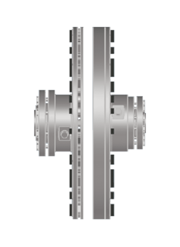
Non-contact magnetic couplings operate on a fundamentally different principle. Because torque is transmitted across an air gap using eddy currents induced by permanent magnets, there is no mechanical interface through which shock loads can propagate. Torque peaks and torsional vibration cannot generate shock loads within the coupling itself because there is nothing to impact. This means selection is based directly on motor power and speed — no service factor calculation is required — resulting in correctly dimensioned couplings rather than oversized ones.
For high-inertia applications where shock loads are most severe, a High Inertia (HI) application variant is available that is specifically positioned as a direct upgrade for fluid-plus-flex starting couplings. The torsional stiffness of a non-contact coupling is effectively zero, which means torsional vibration is absorbed rather than transmitted, and radial stiffness is also zero, structurally eliminating misalignment-induced reaction forces from the drivetrain entirely.
Choose a non-contact magnetic drive when:
- Shock loads are frequent, severe, or occur in unpredictable process conditions
- The application involves high-inertia loads, hard-starting equipment, or cavitation-prone pumps
- The installation is in a hazardous area where conventional coupling wear introduces ignition risk
- Maintenance access is limited and coupling wear components are difficult to replace
- You need soft-start capability without the complexity and losses of a variable frequency drive
Install a non-contact magnetic drive for shock absorption
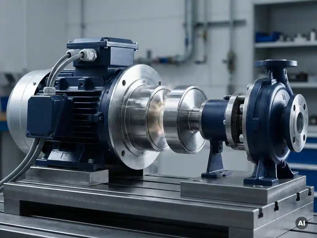
Once you have selected a non-contact magnetic drive as your protection method, installation is straightforward. One of the practical advantages of this technology is that it is designed as a functional drop-in retrofit for all conventional coupling types, reusing the existing motor, motor cabling, and baseplate where possible.
Follow this installation sequence:
- Confirm the motor power and speed from the nameplate and use the catalogue selection tables to identify the correct frame size and torque designation. No service factor calculation is needed — select directly from the IEC 50 Hz or NEMA 60 Hz tables based on rated power and speed.
- Remove the existing coupling. If the existing baseplate is reused, verify that the motor position allows for the required distance between shaft ends (DBSE) and the specified air gap range for the selected coupling size.
- Mount the Inductor Rotor on the motor shaft and the Magnet Rotor on the driven shaft using slip-fit clearance-fit hubs and shrink disc mounting. No laser alignment is required during installation — the non-contact operating principle accommodates shaft misalignment by design.
- Set the air gap within the specified range for your selected frame size. The air gap determines the torque transmission characteristics and should be set according to the catalogue dimensional data for your specific model.
- Verify that no physical contact exists between the rotating components before energizing the motor.
After installation, perform a controlled startup and observe the drivetrain behavior. You should notice smoother acceleration, reduced vibration at the motor and driven equipment bearings, and the absence of the mechanical impact sounds that typically accompany shock events in contact-coupled systems. If vibration levels are measurably higher than expected, recheck the air gap setting and hub mounting before investigating further.
Verify protection performance after installation
Installing a non-contact magnetic drive is not the final step — confirming that it is delivering the expected protection is equally important. Verification gives you documented evidence of improvement and establishes a new baseline for ongoing condition monitoring.
Conduct the following checks within the first two weeks of operation:
- Take vibration measurements at the motor bearings, coupling location, and driven equipment bearings, and compare them against your pre-installation baseline. Vibration reduction of up to 80% is achievable with non-contact drives, particularly in applications where misalignment was a contributing factor.
- Monitor motor current during startup and during any process conditions that previously caused shock events. Smoother current profiles during startup indicate that the soft-start effect of the magnetic coupling is functioning correctly.
- Inspect the driven equipment bearings and seals after the first 30 days of operation. In previously shock-loaded systems, early bearing wear is common. Confirming that wear has not progressed after installation validates that shock transmission has been eliminated.
- If the application involved recurring coupling failures, note the date of installation and track the interval to the first coupling-related maintenance event. Compare this against your historical average replacement interval.
Document all measurements and observations in your maintenance management system. This record supports future reliability reviews and provides the data needed to calculate the return on investment of the protection upgrade.
Maintain long-term shock protection with minimal intervention
One of the most significant operational advantages of non-contact magnetic drives for shock load protection is the near-elimination of coupling maintenance. Conventional couplings in shock-loaded applications require regular inspection, wear element replacement, and in many cases lubrication. Each maintenance intervention requires personnel to work near rotating equipment, which carries its own safety and operational risk.
Non-contact couplings contain no wear components within the coupling itself, no elastomers, no lubricants, and no mechanical interfaces that degrade under repeated shock events. The wear component lifespan is rated at over 20 years under normal operating conditions, and no coupling maintenance or lubrication is required during that period.
To maintain long-term shock protection, focus your ongoing monitoring on the driven equipment and motor rather than the coupling:
- Continue periodic vibration monitoring on motor and driven equipment bearings to detect any changes in the process that might indicate new shock load sources developing
- Monitor motor temperature and current draw for trends that could indicate changes in load characteristics
- Inspect the air gap visually during planned shutdowns to confirm no external forces have caused axial displacement of the motor or driven equipment
- Review your maintenance records annually to confirm that coupling-related failures have been eliminated and that bearing and seal replacement intervals have extended
The reduced intervention requirement also means fewer hours of exposure for maintenance personnel near rotating equipment, which reduces safety risk and frees maintenance capacity for other priorities across the plant.
How Zytec helps protect your motors from shock loads
Zytec's non-contact drives are purpose-built for exactly the kind of shock load protection this guide describes. Where conventional couplings manage shock by absorbing or limiting it through physical contact, Zytec's technology eliminates the transmission pathway entirely. The result is a drivetrain that is structurally immune to shock load propagation rather than merely tolerant of it.
Here is what Zytec's solution delivers in practice:
- Zero torsional and radial stiffness — shock loads and torsional vibration cannot propagate through the coupling because there is no mechanical contact
- No service factor oversizing — coupling selection is based directly on motor power and speed, resulting in correctly dimensioned, lower-inertia drivetrains
- Soft-start capability built in — high-inertia and hard-starting applications benefit from smooth, controlled acceleration without additional starting equipment
- ATEX-certified variants available — the F-TORQ.EX series covers Zone 1 and Zone 2 hazardous areas without the ignition risks associated with contact coupling wear
- Drop-in retrofit design — installs on existing motors and baseplates with no laser alignment required, minimizing installation time and cost
- Over 20-year wear component lifespan — maintenance-free coupling operation that reduces personnel exposure and maintenance cost over the asset lifecycle
If your rotating equipment is suffering from recurring shock-related failures, or if you are planning a new installation in a demanding application, contact Zytec to discuss which non-contact drive solution fits your specific operating conditions.
Frequently Asked Questions
How do I know if my motor is already experiencing shock load damage before any visible failure occurs?
Early warning signs include elevated vibration readings at motor or driven equipment bearings, abnormal noise during startup or process transitions, progressive misalignment that keeps returning after correction, and unexpectedly short bearing or seal service life. The most reliable early detection method is establishing a vibration baseline and trending it over time — a gradual upward drift in vibration amplitude at the coupling end of the motor is a strong indicator of cumulative shock load damage before a catastrophic failure occurs.
Can a non-contact magnetic drive be used on a motor controlled by a variable frequency drive (VFD)?
Yes, non-contact magnetic drives are compatible with VFD-controlled motors. Because torque is transmitted across an air gap using eddy current induction, the coupling does not introduce any electrical feedback or interference into the drive system. However, it is worth noting that if soft-start capability is the primary reason a VFD was installed, a non-contact magnetic drive may allow you to simplify the control system, since controlled acceleration is an inherent characteristic of the magnetic coupling itself.
What happens if a shock event exceeds the torque rating of a non-contact magnetic drive?
Unlike mechanical torque limiters that physically disconnect or shear under overload, a non-contact magnetic drive responds to torque overload by allowing the rotor to slip — the magnetic coupling naturally decouples when the transmitted torque exceeds the peak torque capacity, and then re-engages smoothly once the overload condition clears. This slip-and-recover behavior protects both the motor and the driven equipment without requiring manual reset or component replacement, making it particularly valuable in applications with unpredictable process upsets.
Is laser alignment still required when retrofitting a non-contact magnetic drive onto existing equipment?
No, laser alignment is not required during installation of a non-contact magnetic drive because the air gap operating principle accommodates shaft misalignment by design — both angular and parallel misalignment are tolerated without generating reaction forces on the motor or driven equipment bearings. This is one of the practical installation advantages over conventional flexible couplings, which still require alignment within defined tolerances to achieve their rated service life and prevent bearing overloading.
How do I calculate the return on investment of upgrading to a non-contact magnetic drive?
Start by tallying your historical annual costs at the target location: coupling replacement parts and labor, bearing and seal replacements attributable to shock loads, unplanned downtime events and their production loss value, and any safety incidents related to coupling maintenance near rotating equipment. Compare this against the installed cost of the non-contact drive and its near-zero ongoing maintenance cost over a 20-year component lifespan. In shock-intensive applications, payback periods of 12 to 24 months are common, with the largest cost driver typically being eliminated unplanned downtime rather than reduced parts spend.
Are non-contact magnetic drives suitable for outdoor or harsh environment installations?
Yes, non-contact magnetic drives are well-suited to outdoor and harsh environment installations. Because the coupling contains no elastomers, lubricants, or wear elements that degrade under UV exposure, temperature cycling, or moisture ingress, the environmental durability is inherently higher than conventional flexible element couplings. For hazardous area installations — such as oil and gas facilities or chemical plants — ATEX-certified variants are available that cover Zone 1 and Zone 2 classifications, eliminating the ignition risk associated with friction and wear in contact couplings.
What is the most common mistake engineers make when trying to address recurring shock load failures?
The most common mistake is applying a higher service factor to the replacement coupling without addressing the root cause of the shock load itself. Oversizing a conventional coupling increases drivetrain stiffness and inertia, which can actually amplify dynamic loads on motor and driven equipment bearings rather than reduce them — leading to the same failure mode recurring on a slightly longer interval. The more effective approach is to first identify and characterize the shock source as described in this guide, then select a protection method that addresses the transmission pathway rather than simply tolerating higher peak loads.