Identify the source of speed-related distortion in your system
Before selecting or adjusting any speed control method, you need to understand where distortion originates. Applying a solution to the wrong source wastes time and money, and can introduce new problems. Speed-related distortion in industrial motor systems typically falls into one of three categories: electrical distortion, mechanical distortion, or drivetrain-induced distortion.
- Electrical distortion includes harmonic currents generated by power electronics, voltage spikes from switching devices, and electromagnetic interference from inverter output. These are common in systems using Variable Frequency Drives (VFDs), where IGBTs switching at high frequency inject harmonics back into the supply and create steep voltage edges (high dV/dt) at the motor terminals.
- Mechanical distortion includes torsional vibration, resonance, and shock loads transmitted through rigid or semi-rigid couplings. When a conventional coupling transfers a torque peak, the motor inertia reacts against it, creating a stress pulse that travels through bearings, seals, and shafts.
- Drivetrain-induced distortion includes misalignment forces, imbalance, and bearing wear that create speed fluctuations at the load shaft even when the motor runs cleanly. This category is frequently overlooked because the motor appears to operate normally while the driven equipment does not.
To identify your category, start with vibration measurements at the motor and driven equipment bearings, review power quality logs at the MCC for harmonic distortion, and inspect coupling condition and shaft alignment. If vibration is highest at the coupling, mechanical distortion is the likely source. If power quality shows total harmonic distortion above acceptable limits or the motor runs rough at partial speed, electrical distortion is the primary issue. Document your findings before moving to the next step, as your diagnosis will directly determine which speed control method is appropriate.
Select the right speed control method for your application
With your distortion source identified, you can now match the correct speed control method to your application. The two dominant approaches for industrial rotating equipment are electronic variable speed drives (VFDs) and mechanical non-contact drives. Each has a distinct performance profile, and selecting the wrong one for your conditions can reintroduce the distortion you are trying to eliminate.
When VFDs are the appropriate choice
VFDs are well suited to applications below 10 kW where a mechanical drive would be physically impractical, and for applications requiring motor speeds above 3,600 rpm. They offer precise digital control and integrate easily with automation systems. However, in environments where electrical distortion is already a concern, VFDs require additional mitigation hardware, including EMC input filters, line reactors, dV/dt output filters, and, in some cases, active harmonic filters. Each of these components adds parasitic losses to the system.
When a non-contact magnetic drive is the appropriate choice
For pumps, fans, compressors, and blowers in the 10 to 375 kW range, a mechanical variable speed drive based on eddy current magnetic coupling technology offers a fundamentally different approach to motor speed control. Because torque is transmitted across an air gap using permanent magnets and induced eddy currents, there is no physical contact between the motor shaft and the driven load. This eliminates the mechanical stress pathway entirely and introduces no electrical harmonics into the supply or the motor windings. For applications in hazardous Ex Zone 1 or Zone 2 environments, the non-contact magnetic drive also avoids the need to install power electronics inside or adjacent to the hazardous area, removing a significant ignition risk.
Use the following criteria to finalize your selection:
- Power range 10 to 375 kW and speeds up to 3,600 rpm: evaluate a non-contact drive as the primary option
- Existing motor is Ex-rated and you want to retain it without inverter-duty upgrades: non-contact drive is compatible without motor replacement
- Primary distortion source is mechanical (torsional vibration, shock loads, misalignment): non-contact coupling removes the transmission path for these forces
- Primary distortion source is electrical harmonics from an existing VFD: add output filtering or consider replacing the VFD with a non-contact drive where the power range allows
- Application requires speeds above 3,600 rpm or power below 10 kW: retain a VFD
Configure slip and torque transmission for smooth speed variation
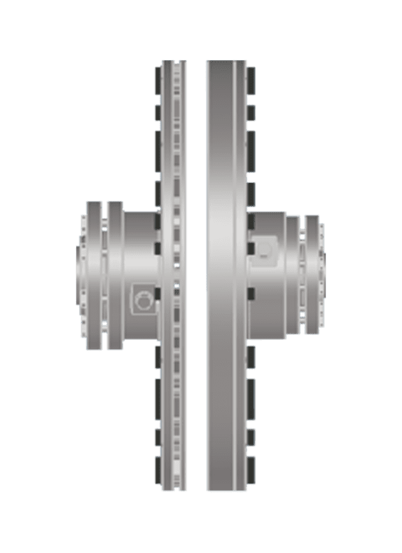
Once you have selected your speed control method, the next step is configuring the operating parameters that govern how speed is varied and how torque is transmitted. In a non-contact magnetic drive, speed variation is achieved by adjusting the air gap between the Inductor Rotor (connected to the motor shaft) and the Magnet Rotor (connected to the driven load). Increasing the air gap reduces the eddy current coupling strength and lowers output speed. Reducing the air gap increases coupling and raises output speed toward the motor's rated speed.
- Confirm the air gap operating range for your drive size. The standard air gap range is 3 to 35 mm, and the output speed range runs from 0 up to approximately 98% of motor rated speed.
- For fixed reduced-speed applications, set the air gap mechanically when the motor is stopped, then lock the position. This is the A-Drive configuration and suits applications where a single reduced speed setpoint is sufficient.
- For continuously variable speed applications, configure the Motor Sliding Base (MSB) actuator to respond to your process control signal. The actuator moves the motor axially to adjust the air gap during operation, providing full variable-speed process control equivalent to a VFD in automatic mode.
- Because there is no mechanical contact, no service factor calculation is required during sizing. Select the coupling directly from the catalogue tables based on motor power and rated speed. Torsional stiffness is effectively zero, which means torque peaks and torsional vibration cannot generate shock loads within the coupling and do not need to be accounted for in the selection.
After configuration, verify that the actuator responds correctly across the full air gap range before connecting the driven load. The output shaft should rotate smoothly with no vibration step changes as the air gap is adjusted from maximum to minimum. If you observe speed instability at a specific gap position, check that the MSB slides freely and that the motor shaft is concentric with the drive axis.
Validate speed output and distortion levels after installation
With your drive installed and configured, validation confirms that the system is performing as intended and that distortion has been reduced to acceptable levels. Do not skip this step, as it also establishes a baseline for future condition monitoring.
- Measure output shaft speed at several setpoints across the operating range using a tachometer or process instrumentation. Confirm that actual speed tracks the commanded setpoint within your process tolerance.
- Take vibration measurements at the motor and driven equipment bearings at each speed setpoint. Compare against your pre-installation baseline. In a correctly installed non-contact drive, radial stiffness between motor and load is zero, meaning misalignment-induced vibration forces are structurally eliminated rather than merely absorbed.
- Record power quality at the MCC supply point. A non-contact drive introduces no power electronics between the supply and the motor, so harmonic distortion levels at the MCC should remain at or below pre-installation levels.
- Check bearing temperatures at the motor and driven equipment after two to four hours of operation at typical load. Elevated temperatures relative to baseline can indicate residual misalignment or a mechanical issue unrelated to the drive.
A successful validation shows stable speed tracking across the operating range, vibration levels at or below baseline, no new harmonic content at the supply, and normal bearing temperatures. If vibration has not improved, recheck shaft alignment between the motor and the driven equipment and confirm that the coupling hubs are correctly seated. If speed tracking is unstable, verify actuator calibration and confirm the MSB slides freely without binding.
Optimize energy efficiency alongside speed control
Speed control and energy efficiency are closely linked, particularly for pump and fan applications where shaft power follows the cubic affinity law. Halving rotational speed reduces shaft power demand to one-eighth, which is why even modest speed reductions produce significant energy savings. However, the overall efficiency of your system depends not only on the drive itself but on the parasitic losses introduced by every component in the power delivery chain.
To optimize energy efficiency in practice:
- Operate at the lowest speed that meets process demand. Avoid running at full speed and throttling downstream with valves or dampers, as this wastes the energy the motor has already converted.
- Audit standby and partial-load losses. In VFD-driven systems, fixed losses from control electronics, cooling fans, and auxiliary systems remain present regardless of load. At 50% load, these fixed losses can represent 40 to 60% of total system losses. A non-contact magnetic drive does not introduce these fixed electrical losses because it contains no power electronics.
- Review your MCC room HVAC load. VFD installations require climate-controlled safe areas with dedicated HVAC, which adds a real parasitic energy cost that is not captured in the drive's published efficiency rating. For a 315 kW class system, these HVAC loads can reach 2 to 4.5% of motor rated power continuously.
- Monitor slip losses in the magnetic drive at your typical operating point. Some slip is inherent to eddy current coupling and represents a small energy cost, but it is predictable and does not increase with age in the way that VFD component degradation does.
With your speed control validated and energy performance baselined, schedule a review at six and twelve months to confirm that efficiency gains are holding. Non-contact drives require no lubrication and no coupling maintenance, which removes a category of maintenance-related energy losses common in conventional drivetrains.
How Zytec helps with motor speed control without distortion
Zytec's non-contact drive technology is purpose-built to solve the distortion, maintenance, and energy challenges described throughout this guide. Rather than adding complexity to your drivetrain, it removes the mechanical contact that causes the problem in the first place. Here is what Zytec brings to each stage of the process:
- No electrical harmonics: The A-TORQ and V-TORQ non-contact drives contain no power electronics, so they introduce zero harmonic distortion into your supply and zero dV/dt stress on motor windings.
- Zero torsional stiffness: Torque peaks and shock loads cannot propagate through the coupling, protecting bearings, seals, and shafts across the entire drivetrain.
- Full variable speed control: The V-TORQ V-Drive adjusts the air gap continuously during operation, delivering process control equivalent to a VFD across the 0 to 98% speed range, without inverter-duty motor upgrades or VFD-rated cabling.
- Energy savings up to 50%: By eliminating overcapacity and enabling precise speed matching to process demand, Zytec drives deliver measurable reductions in electricity consumption, often with a payback period under two years.
- Maintenance-free operation: No lubrication, no coupling wear components, and no scheduled coupling maintenance for the product's rated service life.
If you are evaluating non-contact magnetic drive technology for your rotating equipment, contact Zytec to discuss your application. Zytec's engineering team can assess your system, confirm the correct drive selection, and provide a detailed business case including projected energy savings and total cost of ownership.
Frequently Asked Questions
Can I retrofit a non-contact magnetic drive onto an existing motor without replacing it?
Yes, in most cases a non-contact magnetic drive can be retrofitted to an existing standard motor without replacement. Because the drive requires no inverter-duty motor upgrades, no VFD-rated cabling, and no changes to motor windings, your existing Ex-rated or standard induction motor can be retained as-is. The coupling mounts between the motor shaft and the driven load within the existing drivetrain footprint, though you should confirm shaft dimensions and power rating against the drive's catalogue specifications before ordering.
How do I know if my system's vibration problem is coming from the drive or from somewhere else in the drivetrain?
The most reliable method is to take vibration measurements at multiple points simultaneously — motor bearings, coupling, and driven equipment bearings — and compare the frequency signatures. If the dominant vibration frequency corresponds to shaft rotational speed or its harmonics and is highest at the driven equipment rather than the motor, drivetrain-induced distortion such as misalignment or imbalance is the likely culprit rather than the drive itself. A post-installation vibration baseline (as described in the validation step) makes this comparison straightforward and helps isolate the source quickly.
What happens if process demand changes frequently — can a non-contact magnetic drive respond quickly enough?
The V-TORQ V-Drive's Motor Sliding Base actuator adjusts the air gap continuously in response to your process control signal, providing dynamic speed variation comparable to a VFD in automatic mode. Response speed depends on actuator travel range and control signal update rate, which are application-configurable. For processes with very rapid, step-change demand profiles (sub-second response requirements), discuss your duty cycle with Zytec's engineering team to confirm the actuator configuration is matched to your control loop.
Is there a meaningful efficiency penalty from the slip inherent in eddy current coupling?
Some slip loss is inherent to eddy current coupling and represents a real but predictable energy cost — typically a small percentage of transmitted power at your normal operating point. Importantly, this slip loss does not increase with age, unlike VFD component degradation or mechanical coupling wear. When you account for the absence of VFD fixed electrical losses, MCC room HVAC loads, and maintenance-related energy losses, the total system efficiency of a non-contact drive is frequently competitive with or better than a VFD installation at the same operating point.
What are the most common mistakes made during installation that can undermine speed control performance?
The two most frequent installation errors are inadequate shaft alignment between the motor and driven equipment, and a Motor Sliding Base that is not sliding freely due to improper mounting or debris. Both issues manifest as speed instability or elevated vibration after commissioning and are straightforward to correct before the driven load is connected. Following the validation checklist in Step 4 — including verifying smooth actuator travel across the full air gap range before connecting the load — catches both problems before they affect process performance.
Can a non-contact magnetic drive be used in classified hazardous areas (ATEX/IECEx zones)?
Yes, this is one of the key application advantages of non-contact magnetic drive technology. Because the drive contains no power electronics, it eliminates the need to install or cable inverter hardware inside or adjacent to Ex Zone 1 or Zone 2 classified areas, removing a significant ignition risk. Your existing Ex-rated motor can be retained, and the drive itself does not introduce new ignition sources into the hazardous zone. Always confirm final zone classification and equipment certification with your safety engineer and the drive supplier before installation.
How soon should I expect to see measurable energy savings, and how do I track them accurately?
Measurable energy savings are typically visible from the first full operating period after commissioning, particularly in pump and fan applications where even a 20–30% speed reduction can cut shaft power demand by 50% or more due to the cubic affinity law. To track savings accurately, record baseline power consumption at the MCC before installation across your typical load profile, then compare against post-installation readings at the same operating conditions. Scheduling a formal review at six and twelve months, as recommended in Step 5, ensures efficiency gains are holding and provides the documented data needed to validate your business case.