Identify your application's core operating requirements
Before comparing technologies, map out the specific demands your application places on a coupling. This step prevents you from evaluating couplings in the abstract and keeps the comparison grounded in real operating conditions. Gather data on the following parameters before moving forward.
- Motor power and speed: Record the rated power in kW or HP and the operating speed in rpm. These values determine the torque range your coupling must handle.
- Load type: Identify whether the driven equipment is a centrifugal pump, fan, compressor, conveyor, or high-inertia machine. High-inertia loads such as crushers and large fans place very different demands on a coupling than variable-flow centrifugal pumps.
- Starting conditions: Determine whether your application requires soft-start capability, frequent starts, or controlled acceleration to protect the driven machine and the electrical supply.
- Misalignment tolerance: Assess how much static and dynamic misalignment is realistically present in your installation. Thermal growth, pipe strain, and foundation movement all contribute to dynamic misalignment during operation, often exceeding installation tolerances by a factor of two to five.
- Environment: Establish whether the installation is in a general industrial environment, a wet or corrosive area, or an ATEX-classified hazardous zone. This has direct implications for which coupling types are permissible.
- Speed control requirement: Decide whether you need fixed-speed torque transmission or variable-speed process control. This is a fork in the road that immediately narrows your options.
Once you have these parameters documented, you have a requirements profile to use as a filter in every subsequent step. Any coupling technology that cannot meet one of these core requirements is eliminated from consideration regardless of its other merits.
Compare fluid and magnetic couplings on key performance factors
With your requirements profile in hand, evaluate how fluid couplings and non-contact magnetic couplings perform against each factor. The differences are significant and go well beyond marketing claims.
Torque transmission and soft-start behavior
Fluid couplings transmit torque hydrodynamically through oil circulating between an impeller and a runner. This gives them inherent soft-start capability and some degree of shock absorption, which is why they have been the traditional choice for high-inertia applications like conveyor drives and large fans. However, the slip inherent in a fluid coupling means that the output shaft always runs slightly slower than the input shaft, resulting in a continuous energy loss that scales with load and operating hours.
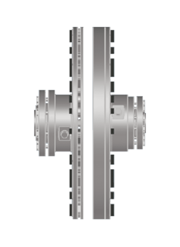
Non-contact magnetic couplings, such as eddy current designs, transmit torque across an air gap using permanent magnets and induced currents. They provide soft-start capability without mechanical contact, and because there is no physical interface between the driving and driven sides, misalignment forces are structurally eliminated rather than merely accommodated. The coupling transmits torque without elastic deformation or sliding contact, which means that none of the operational deviations that occur in real installations introduce forces into bearings or seals downstream.
Misalignment capacity
Fluid couplings are relatively tolerant of minor misalignment because the oil medium absorbs some vibration, but they still maintain a mechanical connection through the fluid housing and shaft attachments. Misalignment ultimately loads the bearings and seals on both sides. Non-contact magnetic couplings can accommodate up to 12 mm of radial dynamic misalignment without transmitting any reaction forces into the drivetrain. This is not a matter of degree but of mechanism: the air gap means there is no force path through which misalignment can propagate.
Overload protection
Both coupling types offer overload protection, but through different mechanisms. A fluid coupling limits torque through slip, which dissipates energy as heat in the oil. In a sustained overload, this generates a significant thermal load and can trigger the coupling's thermal protection (melting plugs in many designs). A non-contact magnetic coupling limits transmitted torque at a defined slip point determined by the magnet configuration, without generating destructive heat within the coupling itself and without any mechanical overload propagation into the drivetrain.
Evaluate maintenance burden and total cost of ownership
The purchase price of a coupling is the smallest element in the lifecycle cost equation. The dominant cost drivers are the downstream consequences of coupling-related failures and the recurring interventions required to keep the coupling operational. This is where fluid couplings and magnetic couplings diverge most sharply.
- List all scheduled maintenance tasks for each coupling type in your application: oil changes, seal inspections, element replacements, laser alignment checks after thermal cycling, and any lubrication requirements.
- Estimate the true cost of each intervention by including lockout/tagout administration, permit-to-work processing, disassembly and reassembly time, precision laser alignment (including soft-foot correction, shimming, and post-thermal re-checks), spare parts logistics, and any contractor coordination required.
- Account for unplanned downtime risk. Misalignment is cited in industry sources as responsible for roughly 30 to 50 percent of rotating machinery failures. Every maintenance intervention on rotating equipment also creates a probability event for human error, including incorrect bolt torque, imperfect alignment, or incorrect reassembly.
- Calculate the total cost of ownership over a realistic asset life, typically 15 to 20 years, not just the first two or three years.
Fluid couplings require periodic oil changes, seal maintenance, and monitoring of thermal protection devices. They also require careful alignment at installation and re-alignment after any maintenance event. Non-contact magnetic couplings contain no elastomers, no lubrication systems, no gear teeth, no friction elements, and no wear components of any kind. Expected service life is the full lifetime of the installation, with a maintenance-free operational span of more than 20 years documented for the coupling itself. The only monitoring required is tracking air gap changes, which serve as an indicator of system-level issues such as bearing degradation or foundation movement rather than coupling wear. This structural difference in maintenance burden translates directly into OPEX reduction that can approach step-change levels in plants where misalignment and maintenance interventions drive a significant share of rotating equipment spend.
Factor in energy efficiency and sustainability targets
Energy performance is increasingly a formal requirement, not just a preference. If your organization has carbon reduction targets, energy audits, or sustainability reporting obligations, coupling selection directly affects your ability to meet them.
Fluid couplings introduce continuous slip losses that are proportional to the speed difference between input and output. In a fixed-speed application, this loss is modest but constant across every operating hour. In variable-speed applications where a fluid coupling is used to throttle flow, the energy waste is substantial because the motor continues to run at full speed while the coupling dissipates the excess energy as heat. Compare this with a non-contact drive configured for variable-speed operation: the air gap between the magnetic rotor and inductor rotor is adjusted to control output speed, which means the motor speed itself can be reduced to match process demand. This approach eliminates the throttling losses inherent in fluid coupling-based speed control and can deliver energy savings of up to 50 percent in pump and fan applications where the system was previously oversized or throttle-controlled.
When documenting your energy case, calculate the annual energy consumption under both scenarios using your actual load profile, not just rated power. The difference in annual kilowatt-hours, multiplied by your energy cost and carbon intensity factor, gives you a concrete sustainability and financial argument for the coupling selection decision.
Apply a decision framework to make your final choice
Bring together everything you have assessed in the previous steps and apply the following decision logic to reach a defensible final choice.
- Filter by environment first. If your installation is in an ATEX Zone 1 or Zone 2 area, fluid couplings introduce oil leakage, oil mist, and thermal event risks that require careful evaluation. Non-contact magnetic couplings certified to ATEX standards operate without oil, seals within the coupling, or any enclosed fluid volume, making them inherently cleaner in explosive atmospheres.
- Filter by speed control requirement. If you need continuous variable-speed control equivalent to a variable frequency drive, a non-contact drive with an adjustable air gap mechanism delivers this without the infrastructure requirements of an electronic drive in a hazardous area. If you need only fixed-speed soft-start and torque limiting, both technologies are viable and you proceed to the next filter.
- Filter by maintenance tolerance. If your plant operates in a regime where coupling maintenance is difficult, costly, or high-risk (remote locations, confined spaces, high-frequency production schedules), the elimination of all scheduled coupling maintenance by a non-contact magnetic coupling is a decisive advantage.
- Filter by misalignment conditions. If your installation experiences significant dynamic misalignment from thermal growth, pipe strain, or foundation movement, a coupling that structurally eliminates misalignment force transmission protects your bearings and seals in a way that no flexible coupling can replicate.
- Validate against TCO. If the non-contact option has a higher initial purchase price, calculate the payback period using your documented maintenance cost reduction and energy savings. In many industrial applications, the payback period is under two years.
After applying these filters, most applications will have a clear preferred technology. Document your reasoning against each criterion so that procurement, engineering, and management all share the same basis for the decision. A coupling selection made on TCO, reliability, and sustainability grounds is far easier to defend than one made on purchase price alone.
How Zytec helps you choose the right coupling
Zytec's non-contact magnetic drives are engineered specifically for the industrial applications described in this guide, including pumps, fans, compressors, conveyors, and generators across sectors ranging from water and wastewater to chemical processing, oil and gas, and mining. Where fluid couplings have traditionally been the default, Zytec's technology offers a direct functional alternative with measurable advantages in reliability, maintenance, and energy performance.
- No scheduled coupling maintenance for the full lifetime of the installation, with a documented maintenance-free span of more than 20 years
- Up to 12 mm of radial dynamic misalignment accommodated without transmitting any reaction forces into bearings or seals
- Energy savings up to 50 percent in oversized or throttle-controlled pump and fan applications
- ATEX-certified variants for Zone 1 and Zone 2 hazardous areas, operating without oil, seals, or enclosed fluid volumes
- Variable-speed capability through the non-contact drive range, providing process control equivalent to a variable frequency drive without the Ex-zone infrastructure requirements
- Drop-in retrofit design that reuses existing motors and cabling, with no laser alignment required during installation
If you are ready to evaluate whether a non-contact magnetic drive is the right fit for your specific application, contact the Zytec team for a technical consultation. Zytec's engineers can run a coupling selection against your motor power, speed, and operating conditions and provide a TCO comparison against your current coupling technology so you have a concrete, data-backed basis for your decision.
Frequently Asked Questions
Can a non-contact magnetic coupling replace a fluid coupling on an existing installation without changing the motor or gearbox?
In most cases, yes. Non-contact magnetic couplings are designed with drop-in retrofit compatibility in mind, reusing the existing motor, shaft centerline, and cabling infrastructure. The key parameters to verify are the shaft diameter, available axial space for the coupling assembly, and the motor's rated torque relative to the coupling's transmission range. A Zytec engineer can confirm dimensional compatibility and produce a retrofit proposal based on your existing equipment data.
What happens if the air gap in a non-contact magnetic coupling changes over time?
A change in air gap is a diagnostic signal, not a failure mode of the coupling itself. It typically indicates bearing wear, foundation settlement, or thermal growth that has shifted the relative position of the motor and driven equipment. Because the coupling transmits no misalignment forces, the drivetrain is protected while the air gap change flags the underlying system-level issue for investigation. Regular air gap monitoring — which requires no disassembly — is the primary condition monitoring task for this coupling type.
How do I calculate whether the energy savings from switching to a non-contact magnetic drive will justify the investment?
Start with your actual load profile: record the motor's operating hours per year, average load factor, and current energy tariff. Estimate the fluid coupling's slip loss as a percentage of transmitted power (typically 2–5% at full load, rising sharply in throttle-controlled applications) and multiply by annual operating hours and energy cost to get a baseline loss figure. For variable-speed applications, apply the affinity laws — reducing pump or fan speed by 20% cuts power demand by roughly 49% — to quantify the additional savings from speed control. Dividing the price difference between coupling options by the annual saving gives you a payback period; in oversized or throttle-controlled systems this is frequently under two years.
Are non-contact magnetic couplings suitable for very high-inertia loads like large crushers or ball mills?
High-inertia applications are a strong use case for non-contact magnetic couplings because the controlled torque transmission during acceleration protects both the motor and the driven machine without relying on fluid heat dissipation. The coupling's torque ceiling is defined by its magnet configuration, so the unit must be correctly sized for the load's inertia and required acceleration time — this is a standard part of the selection process. For extremely large or specialist high-inertia machines, a detailed application review with the manufacturer is recommended before finalizing the specification.
What are the most common mistakes engineers make when selecting between these two coupling technologies?
The most frequent mistake is selecting on purchase price rather than total cost of ownership, which systematically undervalues the maintenance, alignment, and downtime costs that accumulate over a 15–20 year asset life. A second common error is treating misalignment as an installation problem to be solved once at commissioning, rather than a dynamic operating condition that persists and changes throughout the machine's life. Finally, engineers often overlook the energy cost of fluid coupling slip in fixed-speed applications because the per-hour loss appears small — but multiplied across thousands of annual operating hours, it becomes a significant and avoidable expense.
Do non-contact magnetic couplings require any special electrical infrastructure or control systems?
No — this is one of their practical advantages over variable frequency drives in many installations. A non-contact magnetic drive connects directly between the motor and the driven load with no power electronics, no control cabinet, no EMC screening requirements, and no harmonic distortion introduced to the supply. In ATEX hazardous areas in particular, this eliminates the substantial cost and complexity of installing Ex-rated VFD enclosures and associated cable routing. Variable-speed control is achieved mechanically by adjusting the air gap, which can be done manually or via a simple actuator linked to a process signal.
How should I present the coupling selection decision to management or procurement teams who are focused on capital expenditure?
Frame the decision around three quantified figures: the annual maintenance cost reduction (including labor, parts, alignment, and permit-to-work administration), the annual energy saving in kilowatt-hours and its monetary value, and the reduction in unplanned downtime risk expressed as avoided production loss. Present these as a payback period and a net present value over the asset's expected life, using a realistic discount rate. A TCO comparison over 15–20 years almost always reverses the apparent cost advantage of the lower-capex option, and having that calculation documented gives procurement and engineering a shared, defensible basis for the decision.