Audit your factory's biggest CO2 sources first
Before you can reduce CO2 emissions in your industrial facility, you need to know where they actually come from. Many factories assume their biggest energy drain is heating or lighting, but in asset-intensive manufacturing environments, rotating equipment, including pumps, fans, compressors, and conveyors, typically accounts for the largest share of electrical consumption and, by extension, carbon output.
Start your audit by gathering 12 months of energy billing data and breaking it down by department, process line, or equipment category. This baseline gives you a reference point for measuring future progress and helps you prioritize where to focus first.
- Collect electricity consumption data for each major piece of equipment or production zone, ideally at the meter or sub-meter level.
- Map each consumption point to a CO2 equivalent using your grid's emissions factor (your energy supplier or national grid operator publishes this).
- Rank your top 10 energy consumers by annual kilowatt-hour usage and calculate the CO2 contribution of each.
- Flag equipment that runs at full speed continuously but serves processes with variable demand - these are your highest-priority optimization targets.
After completing this step, you should have a ranked list of CO2 contributors with clear data behind each one. If you find that rotating equipment dominates the list, that is entirely typical in industrial settings and means the next steps will have an outsized impact on your overall factory carbon footprint reduction.
Optimize rotating equipment for energy efficiency
Rotating equipment is the backbone of most industrial processes, and it is also one of the most significant sources of avoidable energy waste. The core problem is overcapacity: motors and drives are frequently sized for peak demand but spend most of their operating hours running at partial load. When a pump or fan runs at full speed to serve a process that only needs 60% of its capacity, the excess energy becomes wasted heat and unnecessary CO2.
The most effective way to address this is to match the speed of rotating equipment to actual process demand rather than running everything at a fixed maximum. This principle, rooted in the cubic affinity law, means that reducing a fan or pump's speed by even 20% can cut its energy consumption by nearly 50%.
- Identify which pumps, fans, and compressors are currently running at fixed speed with flow or pressure controlled by throttling valves or dampers - these are immediate candidates for variable-speed operation.
- Review process demand profiles over a typical week. If demand varies by more than 20%, the equipment is a strong candidate for speed optimization.
- Evaluate variable-speed solutions appropriate to your environment. In standard industrial settings, this includes both electronic and mechanical variable-speed drives. In hazardous or Ex-rated zones, the installation complexity and cost of electronic drives increase substantially, making mechanical alternatives worth evaluating on a total cost basis.
- Calculate the projected energy savings using your baseline consumption data and the affinity law. Even conservative estimates typically show payback periods under two years for well-matched applications.
Once you have implemented variable-speed control on your priority equipment, monitor actual energy consumption against your baseline over the following 30 to 60 days. A meaningful reduction in kWh consumption confirms the optimization is working. If savings fall short of projections, check whether the process control setpoints have been adjusted to take advantage of the new speed range.
Reduce mechanical losses across your drivetrain
Even well-sized, variable-speed equipment loses energy before it reaches the process it is driving. Mechanical losses in the drivetrain, caused by friction, misalignment, vibration, and worn coupling elements, quietly consume electricity that never contributes to useful work. In many facilities, these losses are invisible because they are embedded in the baseline consumption figures rather than measured separately.
Misalignment alone is cited in industry sources as responsible for a significant share of rotating machinery failures and associated energy waste. When a coupling transmits torque under misaligned conditions, it introduces additional bearing loads, torsional oscillations, and heat, all of which translate directly into excess energy consumption and accelerated wear.
Inspect and correct alignment across priority equipment
Begin with the rotating equipment identified as your top energy consumers in the audit phase. For each unit, check shaft alignment using laser alignment tools and correct any radial or angular offset. Even small misalignments that appear within acceptable tolerances can generate measurable losses at scale across a large facility.
- Schedule alignment checks during the next planned maintenance window for each priority machine.
- Document pre- and post-correction alignment readings so you have a record of the improvement.
- Inspect coupling elements for wear, cracking, or deformation - worn elastomers and flexible elements increase torsional losses and vibration transmission.
- Replace worn coupling components and re-check alignment after reassembly, as coupling replacement often introduces new offset.
Evaluate non-contact drive technology for persistent loss points
For equipment where misalignment recurs due to thermal expansion, pipe strain, or foundation movement, conventional couplings require repeated realignment interventions. Each intervention carries both a direct maintenance cost and the risk of introducing new misalignment. Non-contact magnetic drive technology eliminates the physical connection between the motor and the driven shaft entirely, transmitting torque across an air gap. This means dynamic misalignment during operation produces no bearing overload, no additional friction losses, and no coupling wear.
After completing drivetrain improvements, verify the outcome by comparing vibration measurements and bearing temperatures against your pre-intervention baseline. Reduced vibration and lower bearing temperatures are reliable indicators that mechanical losses have decreased.
Track and measure your CO2 reduction progress
Sustainable factory operations require sustained measurement. Without a structured approach to tracking, energy savings erode over time as equipment degrades, processes change, and new inefficiencies creep in. Measurement also gives you the data you need to report progress internally, to customers, and to regulators.
Establish a monitoring routine that connects energy consumption directly to production output, not just to calendar time. Normalizing consumption per unit of production, per tonne processed, or per operating hour gives you a metric that remains meaningful even when production volumes fluctuate.
- Install sub-metering on your top energy consumers if it is not already in place. This is the single most important infrastructure investment for ongoing CO2 tracking.
- Define your key performance indicator: kWh per unit of output is the most practical starting point for most manufacturing environments.
- Set a monthly review cadence where you compare current performance against your pre-intervention baseline and against your reduction targets.
- Flag any equipment where consumption has increased relative to the baseline - this often indicates a developing mechanical fault, process change, or control system issue.
- Translate your energy reduction figures into CO2 equivalents monthly, using your grid's current emissions factor, and record these for reporting purposes.
After the first three months of structured tracking, you should have enough data to identify whether your improvements are holding, improving further as equipment settles into optimized operation, or beginning to drift. Use this data to inform your maintenance schedule and to build the business case for the next phase of investment.
Scale improvements across your entire facility
With verified results from your priority equipment, you are now in a position to apply the same methodology systematically across the rest of your facility. Scaling is where the largest absolute CO2 reductions happen, but it requires a structured approach to avoid spreading resources too thin or implementing changes without adequate data.
Use the performance data from your initial improvements as an internal benchmark. If variable-speed optimization on a 75 kW pump delivered a 35% energy reduction, that figure becomes your reference for evaluating similar equipment elsewhere in the plant. This makes the business case for each subsequent investment faster to build and easier to approve.
- Return to your original ranked list of CO2 contributors and identify the next tier of equipment that shares characteristics with your successful pilot installations.
- Group equipment by type and application so you can standardize your approach - the same solution that worked for one centrifugal pump is likely to work for similar pumps running under comparable conditions.
- Develop a rolling implementation schedule that aligns with planned maintenance windows to minimize production disruption.
- Build an internal knowledge base documenting what worked, what the measured outcomes were, and what installation or commissioning steps were critical to success.
- Engage your maintenance and engineering teams early in each new implementation - their operational knowledge of specific equipment is essential for accurate baselining and realistic savings projections.
As you scale, revisit your facility-wide CO2 audit annually. Process changes, new equipment additions, and shifts in production mix will alter your consumption profile over time. An annual audit ensures your reduction strategy stays aligned with where the actual emissions are coming from, rather than where they were when you started.
How Zytec helps reduce your factory's CO2 footprint
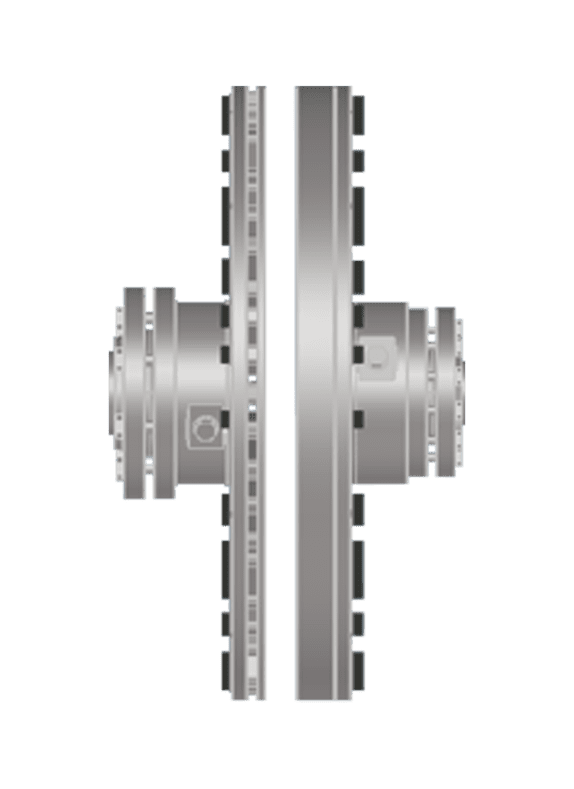
Zytec's non-contact magnetic drives directly address the energy losses and mechanical inefficiencies described throughout this guide. Where conventional drivetrains waste energy through friction, misalignment, and overcapacity, Zytec's technology eliminates the physical contact between motor and driven equipment entirely, transmitting torque across a magnetic air gap with no wear, no lubrication, and no alignment-induced losses.
- Energy savings up to 50%: The A-TORQ Non-Contact Drive eliminates overcapacity in pump and fan applications by enabling smooth, continuous speed control without the parasitic losses associated with throttling or electronic drive systems.
- Vibration reduction up to 80%: By decoupling the motor from the drivetrain mechanically, Zytec drives eliminate the torsional oscillations and bearing overloads that waste energy and accelerate component wear.
- Maintenance-free operation for 20+ years: No coupling elements to replace, no realignment requirements, and no lubrication intervals mean fewer interventions, lower maintenance costs, and a structurally lower total cost of ownership.
- Payback period typically under 2 years: The combination of energy savings and eliminated maintenance spend produces a rapid return on investment that makes the business case straightforward to build.
- Drop-in retrofit compatibility: Zytec drives are designed to reuse existing motors and cabling, minimizing installation complexity and downtime during upgrades.
If you are ready to take the next step toward measurable, sustainable CO2 reduction in your facility, contact Zytec to discuss which non-contact drive solution fits your specific application and energy profile.
Frequently Asked Questions
How do I calculate the CO2 emissions factor for my facility if my energy supplier doesn't publish one?
If your energy supplier doesn't publish an emissions factor directly, you can use your national grid operator's published average grid intensity figure, which is typically expressed in grams of CO2 per kilowatt-hour (gCO2/kWh). In Europe, the European Environment Agency publishes country-specific grid emissions factors annually. For a more precise figure, particularly if you purchase renewable energy under a Power Purchase Agreement (PPA) or use on-site generation, you may be able to apply a market-based emissions factor instead of the grid average — your sustainability consultant or energy auditor can help you determine which approach is appropriate for your reporting framework.
What if our production processes run 24/7 with no planned downtime — how do we implement these changes without disrupting output?
Continuous production environments require a phased approach tied to any available maintenance windows, even brief ones. Start by prioritizing equipment that has a redundant unit or a bypass configuration, so one machine can be taken offline while the other maintains process continuity. For truly critical single-point equipment, technologies like Zytec's non-contact magnetic drives are particularly well-suited because their drop-in retrofit design minimizes installation time, and in many cases the changeover can be completed within a standard shift turnaround. Building your implementation schedule around annual statutory inspections or planned shutdowns is the most practical way to achieve zero-disruption upgrades.
How do we handle the business case for CO2 reduction investments when energy prices fluctuate so much?
The key is to model your payback calculations using a conservative, floor-level energy price rather than current spot prices, so the business case holds even in a lower-price scenario. For rotating equipment optimizations specifically, the savings case is reinforced by the non-energy benefits — reduced maintenance spend, extended bearing and coupling life, and lower unplanned downtime costs — which are largely independent of energy price movements. Presenting the investment as a combined energy-plus-maintenance cost reduction, rather than an energy-only play, makes the financial case more robust and easier to approve at board level.
Are there specific industries or factory types where this approach delivers the biggest CO2 reductions?
The methodology in this guide delivers the highest impact in asset-intensive industries where rotating equipment runs continuously at high load: water and wastewater treatment, chemical processing, food and beverage manufacturing, HVAC-heavy facilities, and mining and minerals processing are consistently the strongest candidates. These sectors tend to have large numbers of pumps, fans, and compressors running at fixed speeds against variable demand, which is precisely the profile where variable-speed optimization and drivetrain loss reduction generate the most significant savings. That said, any facility where rotating equipment accounts for more than 40% of total electrical consumption will typically see strong results from this approach.
What are the most common mistakes factories make when trying to reduce their carbon footprint?
The most frequent mistake is skipping the audit phase and jumping straight to technology purchases based on assumptions rather than data — this often results in investing in the wrong equipment or the wrong areas. A close second is measuring savings against calendar time rather than production output, which makes it impossible to distinguish genuine efficiency gains from reductions caused by lower production volumes. Finally, many facilities treat CO2 reduction as a one-off project rather than an ongoing operational discipline, which means savings erode within 12 to 18 months as equipment degrades and process conditions shift without anyone tracking the drift.
How does non-contact magnetic drive technology perform in hazardous or ATEX-rated zones compared to electronic variable-speed drives?
In ATEX or other Ex-rated hazardous zones, electronic variable-speed drives require significantly more complex and costly installation — including explosion-proof enclosures, conduit sealing, and additional safety certification — which can push payback periods well beyond two years and increase project risk. Mechanical non-contact magnetic drives, by contrast, have a simpler installation footprint with no electronics in the drive unit itself, which can make ATEX compliance more straightforward and the overall project cost lower. It's worth conducting a full total cost of ownership comparison for any hazardous-zone application, factoring in installation complexity, ongoing maintenance requirements, and the cost of any additional safety infrastructure each technology requires.
Once we've achieved our initial CO2 reduction targets, what are the logical next steps to continue cutting our factory's emissions?
After optimizing rotating equipment and drivetrain efficiency, the natural next steps are to address thermal energy losses — process heating, steam systems, and compressed air generation — which often become the dominant CO2 sources once electrical consumption has been reduced. Beyond that, integrating on-site renewable generation (rooftop solar, for example) and exploring electrification of any remaining fossil-fuel-powered processes can drive your Scope 1 emissions toward zero. It's also worth engaging your supply chain at this stage: once your own operational emissions are under control, Scope 3 emissions from purchased materials and logistics typically represent the largest remaining lever for reducing your total carbon footprint.